


b. Remove and discard UPPER (molded) inducer housing
drain tube which was previously connected to conden-
sate trap.
c. Install cap and clamp on UPPER inducer housing drain
connection where molded drain tube was removed.
d. Use inducer housing drain extension tube (violet label
and factory-supplied in loose parts bag) to connect
LOWER inducer housing drain connection to conden-
sate trap.
e. Determine appropriate length, cut, and connect tube to
condensate trap.
f. Clamp tube to prevent any condensate leakage.
3. Relief Port Tube:
Refer to Pressure Switch Tubing section for connection
procedure.
C.
Condensate Trap Field Drain Attachment
Refer to Condensate Drain section for recommendations and
procedures.
D.
Pressure Switch Tubing
One collector box pressure tube (pink label) is factory connected to
the High Pressure Switch for use when furnace is installed in
UPFLOW applications. This tube MUST be disconnected and used
for the condensate trap relief port tube. The other collector box
pressure tube (green label) which was factory connected to the
condensate trap relief port connection MUST be connected to the
High Pressure switch in DOWNFLOW or HORIZONTAL RIGHT
applications.
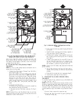
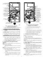
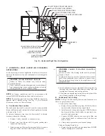
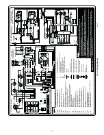
NOTE:
See Fig. 12 or tube routing label on main furnace door to
check for proper connections.
Relocate tubes as described below.
1. Disconnect collector box pressure tube (pink label) attached
to High Pressure Switch.
2. Extend collector box pressure tube (green label) which was
previously connected to condensate trap relief port connec-
tion by splicing to small diameter tube (factory-supplied in
loose parts bag).
3. Connect collector box pressure tube (green label) to High
Pressure Switch connection labeled COLLECTOR BOX.
4. Use remaining smaller diameter tube (factory-supplied in
loose parts bag) to extend collector box pressure tube (pink
label) which was previously connected to High Pressure
Switch. Route this extended tube (pink label) to condensate
trap relief port connection.
5. Determine appropriate length, cut, and connect tube.
6. Clamp tube to relief port connection.
E.
Condensate Trap Freeze Protection
Refer to Condensate Drain Protection section for recommenda-
tions and procedures
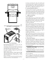
F.
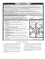
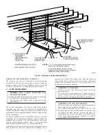
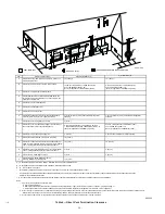
Construct a Working Platform
Construct working platform where all required furnace clearances
are met. (See Fig. 3 and 11.)
CAUTION:
UNIT MAY NOT OPERATE
Failure to follow this caution may result in intermittent
unit operation
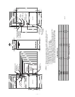
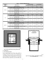
The condensate trap MUST be installed below furnace.
See Fig. 5 for dimensions. The drain connection to
condensate trap must also be properly sloped to an open
drain.
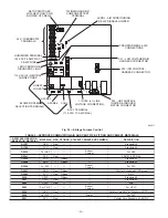
NOTE:
Combustion-air and vent pipes are restricted to a mini-
mum length of 5 ft. (See Table 7.)
NOTE:
A 12-in. minimum offset pipe section is recommended
with short (5 to 8 ft) vent systems. This recommendation is to
reduce excessive condensate droplets from exiting the vent pipe.
(See Fig. 11 or 34.)
LOCATION
I.
GENERAL
This furnace must
•
be installed so the electrical components are protected from
water.
•
not be installed directly on any combustible material other than
wood flooring (refer to SAFETY CONSIDERATIONS).
•
be located so combustion-air and vent pipe maximum lengths
are not exceeded. Refer to Table 7.
•
be located where available electric power and gas supplies meet
specifications on the furnace rating plate.
•
be attached to an air distribution system and be located as close
to the center of the distribution system as possible. Refer to Air
Ducts section.
•
be provided with ample space for servicing and cleaning.
Always comply with minimum fire protection clearances
shown on the furnace Clearance to Combustibles label.
This furnace may be located in a confined space without special
provisions for dilution or ventilation air.
When a furnace is installed so that supply ducts carry air circulated
by the furnace to areas outside the space containing the furnace,
return air must also be handled by ducts sealed to furnace casing.
The ducts terminate outside the space containing the furnace to
ensure there will not be a negative pressure condition within
equipment room or space.
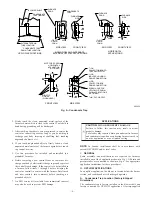
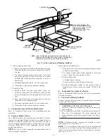
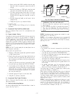
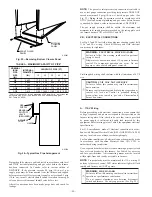
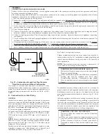
NOTE:
For upflow/downflow applications install furnace so that
it is level or pitched forward within 1/2-in. for proper furnace
operation. For horizontal applications pitch 1/4-in. minimum to
1/2-in. maximum forward to ensure proper condensate drainage
from secondary heat exchangers. (See Fig. 13.)
Fig. 13—Proper Condensate Drainage
A02146
UPFLOW OR DOWNFLOW
HORIZONTAL
FRONT
LEVEL (0
″
)
TO
1
⁄
2
″
MAX
MIN
1
⁄
4
″
TO
1
⁄
2
″
MAX
FRONT
—13—
Содержание CONDENSING GAS FURNACE 352MAV
Страница 51: ...51...


