


WARNING:
ELECTRICAL SHOCK HAZARD
Failure to follow this warning could result in electrical
shock, fire, or death.
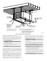
The furnace casing MUST have an uninterrupted or
unbroken ground according to NEC ANSI/NFPA 70-
2002 and Canadian Electrical Code CSA C22.1 or local
codes to minimize personal injury if an electrical fault
should occur. This may consist of electrical wire or
conduit approved for electrical ground when installed in
accordance with existing electrical codes. Do not use gas
piping as an electrical ground.
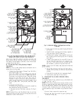
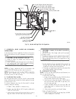
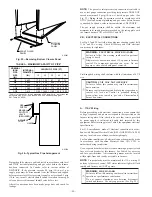
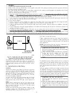
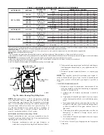
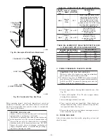
J-BOX RELOCATION
1. Remove 2 screws holding auxiliary J-box. (See Fig. 30.)
2. Rotate J-box 180° and attach box to left side, using holes
provided.
WARNING:
FIRE
OR
ELECTRICAL
SHOCK
HAZARD
Failure to follow this warning could result in intermittent
unit operation or performance satisfaction.
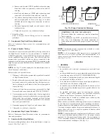
If manual disconnect switch is to be mounted on furnace,
select a location where a drill or fastener will not contact
electrical or gas components.
B.
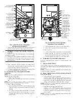
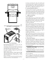
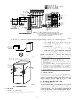
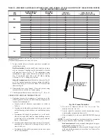
24-V Wiring
Make field 24-v connections at 24-v terminal block. (See Fig. 32.)
Connect terminal Y/Y2 as shown in Fig. 27 and 28 for proper
cooling operation. Use only AWG No. 18, color-coded, copper
thermostat wire for lengths up to 100 ft. For wire lengths over 100
ft, use AWG No. 16 wire.
The 24-v circuit contains an automotive-type, 3-amp fuse located
on furnace control (See Fig. 32.) Any direct shorts of 24-v wiring
during installation, service, or maintenance could cause this fuse to
blow. If fuse replacement is required, use ONLY a 3-amp fuse of
identical size/type. The control will flash code 24 when fuse needs
replacement.
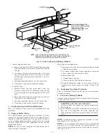
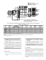
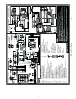
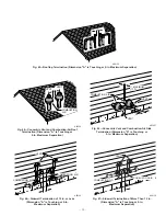
Fig. 27—Heating and Cooling Application Wiring Diagram 1-Stage Thermostat and Condensing Unit
A99071
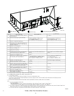
115-V FUSED
DISCONNECT
SWITCH
(WHEN REQUIRED)
JUNCTION
BOX
CONTROL
BOX
24-V
TERMINAL
BLOCK
TWO-WIRE
HEATING-
ONLY
FIVE
WIRE
1-STAGE THERMOSTAT TERMINALS
FIELD-SUPPLIED
FUSED DISCONNECT
CONDENSING
UNIT
FURNACE
COM
R
W
Y
R
G
C
GND
GND
GND
GND
GND
GND
FIELD 24-V WIRING
FIELD 115-, 208/230-, 460-V WIRING
FACTORY 24-V WIRING
FACTORY 115-V WIRING
208/230- OR
460-V
THREE
PHASE
208/230-V
SINGLE
PHASE
WHT
BLK
WHT
BLK
W/W1
W2
Y/Y2
G
NOTES:
1. Connect Y-terminal as shown for proper operation.
2. Some thermostats require a "C" terminal connection as shown.
3. If any of the original wire, as supplied, must be replaced,
use same type or equivalent wire.
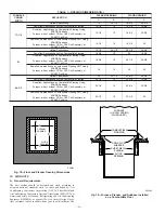
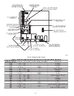
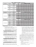
TABLE 4—ELECTRICAL DATA
UNIT
SIZE
VOLTS—
HERTZ—
PHASE
OPERATING
VOLTAGE RANGE
MAX
UNIT
AMPS
UNIT
AMPACITY†
MIN
WIRE
SIZE
MAX WIRE
LENGTH
(FT)‡
MAX FUSE
OR CKT BKR
AMPS**
Max*
Min*
036060
115-60-1
127
104
8.4
11.3
14
33
15
036080
115-60-1
127
104
8.1
10.8
14
34
15
048080
115-60-1
127
104
11.6
15.3
12
37
20
048100
115-60-1
127
104
11.6
15.4
12
37
20
060100
115-60-1
127
104
13.3
17.5
12
33
20
060120
115-60-1
127
104
12.9
16.8
12
34
20
* Permissible limits of voltage range at which unit will operate satisfactorily.
† Unit ampacity = 125 percent of largest operating component’s full load amps plus 100 percent of all other potential operating components’ (EAC, humidifier, etc.) full load
amps.
‡ Length shown is a measured 1 way along wire path between unit and service panel for maximum 2 percent voltage drop.
** Time-delay type is recommended.
—21—
Содержание CONDENSING GAS FURNACE 352MAV
Страница 51: ...51...


