
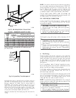
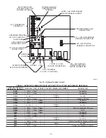


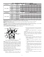
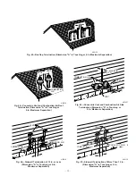
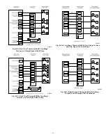
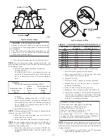

3. Loosely install elbow in bracket and place assembly on
combustion-air pipe.
Roof terminations-Loosely install pipe coupling on prop-
erly cut vent pipe. Coupling must be positioned so bracket
will mount as shown in Fig. 37. For applications using
combustion-air pipe option, indicated by dashed lines in
Fig. 37, install 90° street elbow into 90° elbow, making
U-fitting. A 180° U-fitting may be used.
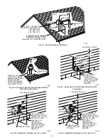
Sidewall terminations-Install bracket as shown in Fig. 40
or 41. For applications using vent pipe option indicated by
dashed lines in Fig. 40, rotate vent elbow 90° from position
shown in Fig. 40.
4. Disassemble loose pipe fittings. Clean and cement using
same procedures as used for system piping.
5. Check required dimensions as shown in Fig. 37, 40, or 41.
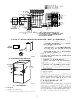
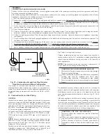
CONCENTRIC VENT/AIR TERMINATION KIT
1. Determine location for termination. Consideration of the
following should be made when determining an appropriate
location for termination kit.
a. Comply with all clearance requirements as stated in
Table 6.
b. Termination kit should be positioned where vent vapors
will not damage plants/shrubs or air conditioning equip-
ment.
c. Termination kit should be positioned so it will not be
affected by wind eddy (such as inside building corners)
or that may allow recirculation of flue gases, airborne
leaves, or light snow.
d. Termination kit should be positioned where it will not be
damaged by or subjected to foreign objects, such as
stones, balls, etc.
e. Termination kit should be positioned where vent vapors
are not objectionable.
2. Cut one 4-in. diameter hole for 2-in. kit, or one 5-in.
diameter hole for 3-in. kit.
3. Loosely assemble concentric vent/air termination compo-
nents together using instructions in kit.
4. Slide assembled kit with rain shield REMOVED through
hole.
NOTE:
Do not allow insulation or other materials to accumulate
inside of pipe assembly when installing it through hole.
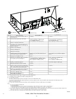
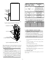
Roof terminations-Locate assembly through roof to appro-
priate height as shown in Fig. 38.
Sidewall terminations-Locate assembly through sidewall
with rain shield positioned no more than 1-in. from wall as
shown in Fig. 39.
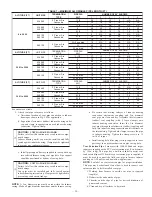
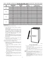
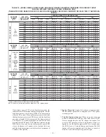
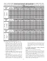
TABLE 8—MAXIMUM ALLOWABLE EXPOSED VENT PIPE LENGTH (FT) WITH AND WITHOUT INSULATIONIN WINTER
DESIGN TEMPERATURE AMBIENT*
UNIT
SIZE
WINTER DESIGN
TEMPERATURE
(°F)
MAX PIPE
DIAMETER
(IN.)
WITHOUT
INSULATION
WITH 3/8–IN. OR
THICKER INSULATION†
060
20
2
44
70
0
2
21
70
-20
2
20
57
080
20
2
55
55
0
2
30
55
-20
2
16
55
20
2.5
58
70
0
2.5
29
70
-20
2.5
14
67
100
20
2.5
40
40
0
2.5
38
40
-20
2.5
21
40
20
3
63
70
0
3
30
70
-20
3
12
70
120
20
3
70
70
0
3
38
70
-20
3
19
70
20
4
65
70
0
4
26
70
-20
4
5
65
* Pipe length (ft) specified for maximum pipe lengths located in unconditioned spaces. Pipes located in unconditioned space cannot exceed total allowable pipe length as
specified in Table 7.
† Insulation thickness based on R value of 3.5 per in.
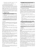
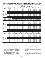
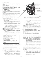
Fig. 42—Freeze Protection
A93058
32
°
F MINIMUM INSTALLED
AMBIENT OR FREEZE
PROTECTION REQUIRED
—33—
Содержание CONDENSING GAS FURNACE 352MAV
Страница 51: ...51...


