HL-3450CN SERVICE MANUAL
8-9
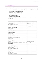
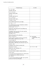
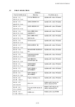
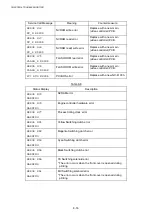
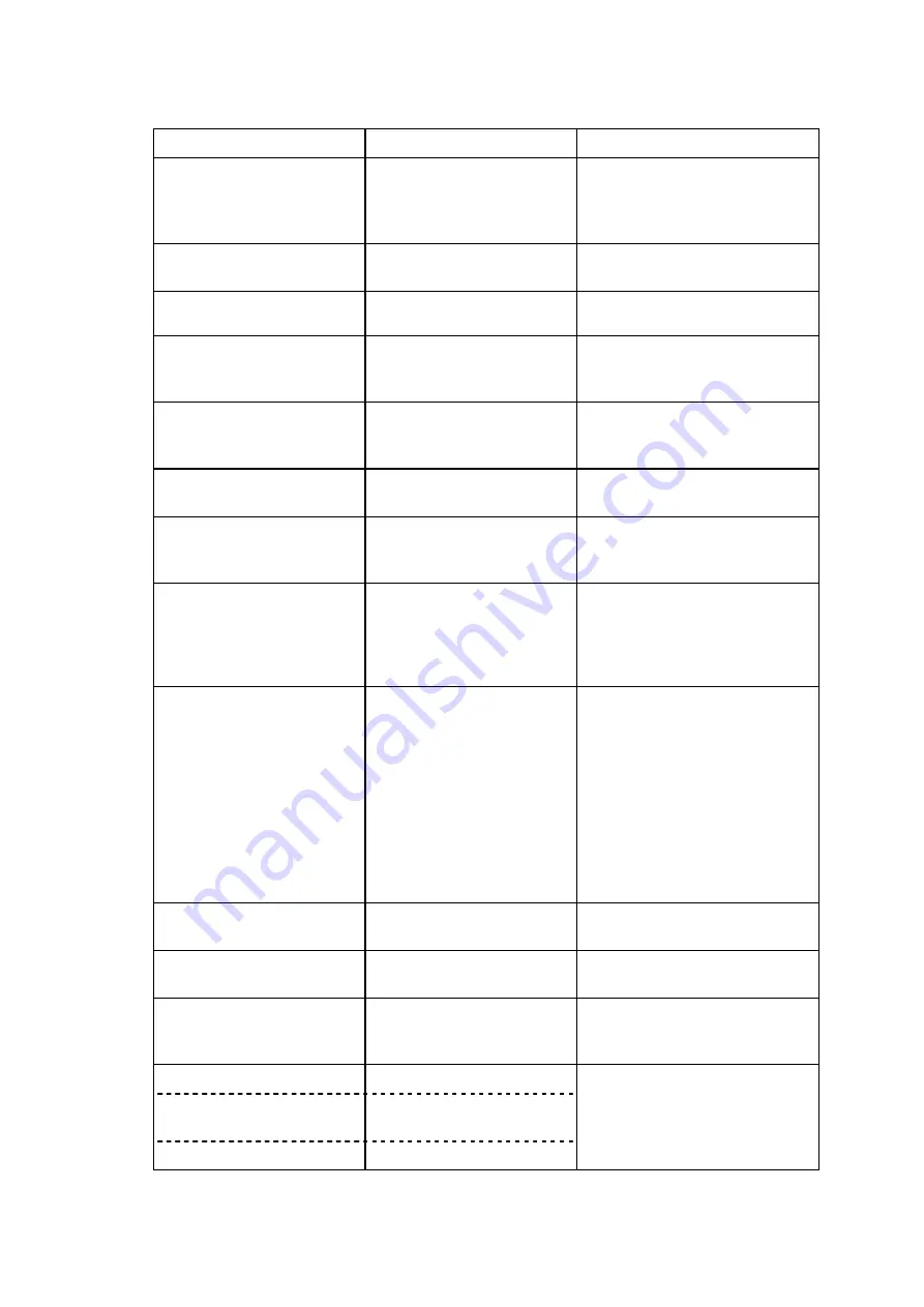
Display Message
Meaning
Countermeasure
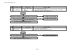
16 ALIGN FU UNIT
Fusing unit not installed
x
Remove the fusing unit and
refit it.
x
Confirm it is correctly
installed.
16 ALIGN BELT CG
OPC belt cartridge not
installed
Confirm the installation of the
OPC belt cartridge.
16 ALIGN FUSER CL
ROLLER
Fuser cleaner not installed.
Install the fuser cleaner.
16 ALIGN LFU
Incorrect connection
between the engine and
fusing unit.
Connect the cable between the
engine and fusing unit correctly.
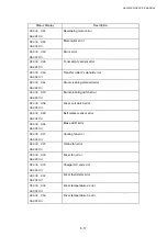
17 MEDIA JAM FEED
Paper jam at feeding area
Remove the media cassette,
and remove paper jammed at
feeding entrance.
17 MEDIA JAM INNER
Paper jam inside printer
Open the transfer unit, and
remove paper jammed inside.
17 MEDIA JAM OUTER
Paper jam at paper exit area Open the transfer unit / paper
exit unit and remove paper
jammed inside.
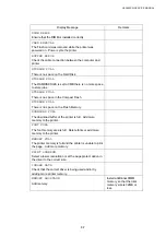
17 MEDIA JAM DRUM
Paper jam wound around
the transfer drum
Open the transfer unit and
remove the OPC belt cartridge.
Remove the paper jam by
unwinding the paper from the
transfer drum.
17 MEDIA JAM DUPLEX
Duplex paper transportation
jam.
x
Open the duplex top cover
and remove the jammed
paper from the inside of the
printer.
x
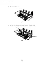
Open the duplex center cover
and remove the jammed
paper from the inside of the
printer.
x
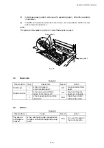
Open the duplex bottom
cover (M) and remove the
jammed paper.
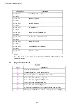
18 CLOSE PANEL
FRONT/TOP/REAR/LFU
Covers open
Confirm that the covers are
firmly closed.
18 CLOSE TR PANEL
DPL
Duplex unit cover is open.
Confirm that the cover is firmly
closed.
19 SLEEP MODE
Printer under idling
condition
Printer automatically returns to
the operating condition when a
PRINT signal is sent.
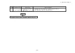
01 WAIT
Printer warming-up
00 READY
Printer ready to print in
standby status
These are normal operation
modes.
02 PRINT
Printing in progress
Содержание HL-3450CN Series
Страница 15: ...HL 3450CN SERVICE MANUAL xiii 3 Rating Label For US For Europe 4 Operation Label 5 Jam Label ...
Страница 17: ...HL 3450CN SERVICE MANUAL CHAPTER 1 PRODUCT OUTLINE ...
Страница 27: ...HL 3450CN SERVICE MANUAL CHAPTER 2 SPECIFICATIONS ...
Страница 39: ...CHAPTER 3 INSTALLATION ...
Страница 54: ...HL 3450CN SERVICE MANUAL CHAPTER 4 STRUCTURE OF SYSTEM COMPONENTS ...
Страница 87: ...CHAPTER 4 STRUCTURE OF SYSTEM COMPONENTS 4 34 Layout of Clutches 2 9 1 3 7 6 5 4 8 10 Fig 4 31 ...
Страница 104: ...HL 3450CN SERVICE MANUAL 4 51 Main PCB Circuit Diagram 1 8 CODE B512137CIR 1 8 LJ8907001 NAME ...
Страница 105: ...CHAPTER 4 STRUCTURE OF SYSTEM COMPONENTS 4 52 Main PCB Circuit Diagram 2 8 CODE B512137CIR 2 8 LJ8907001 NAME ...
Страница 106: ...HL 3450CN SERVICE MANUAL 4 53 Main PCB Circuit Diagram 3 8 CODE B512137CIR 3 8 LJ8907001 NAME ...
Страница 107: ...CHAPTER 4 STRUCTURE OF SYSTEM COMPONENTS 4 54 Main PCB Circuit Diagram 4 8 CODE B512137CIR 4 8 LJ8907001 NAME ...
Страница 108: ...HL 3450CN SERVICE MANUAL 4 55 Main PCB Circuit Diagram 5 8 CODE B512137CIR 5 8 LJ8907001 NAME ...
Страница 109: ...CHAPTER 4 STRUCTURE OF SYSTEM COMPONENTS 4 56 Main PCB Circuit Diagram 6 8 CODE B512137CIR 6 8 LJ8907001 NAME ...
Страница 110: ...HL 3450CN SERVICE MANUAL 4 57 Main PCB Circuit Diagram 7 8 CODE B512137CIR 7 8 LJ8907001 NAME ...
Страница 111: ...CHAPTER 4 STRUCTURE OF SYSTEM COMPONENTS 4 58 Main PCB Circuit Diagram 8 8 CODE B512137CIR 8 8 LJ8907001 NAME ...
Страница 112: ...HL 3450CN SERVICE MANUAL 4 59 Network Board PCB Circuit Diagram CODE LJ8107001 NAME B512058CIR ...
Страница 114: ...HL 3450CN SERVICE MANUAL 4 61 TAB2 HP TAB1 HN ACN4 ACN1 ACN3 ACN2 ACN5 Inlet Black White Power Switch Fig 4 40 ...
Страница 126: ...HL 3450CN SERVICE MANUAL CHAPTER 5 CONTROL PANEL OPERATION ...
Страница 173: ...HL 3450CN SERVICE MANUAL CHAPTER 6 PERIODIC MAINTENANCE ...
Страница 208: ...CHAPTER 7 DISASSEMBLY RE ASSEMBLY ...
Страница 264: ...HL 3450CN SERVICE MANUAL CHAPTER 8 TROUBLESHOOTING ...
Страница 310: ...HL 3450CN SERVICE MANUAL 8 47 5 IMAGE FAILURE 1 2 3 4 5 6 7 8 9 a 9 b 10 11 12 13 14 ...
Страница 311: ...CHAPTER 8 TROUBLESHOOTING 8 48 15 a 15 b 16 17 18 19 20 21 22 23 24 25 26 27 28 244m m 29 ...

