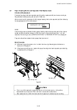
CHAPTER 6 PERIODIC MAINTENANCE
6-18
2.10
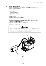
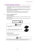
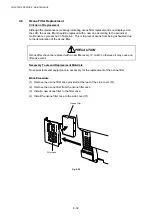
Cleaning the Oil Pad
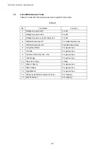
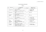
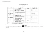
The oil pad should be cleaned according to the periodic maintenance cleaning cycle set out
in Table 6-3.
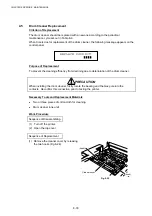
When time is due for replacement of the oil pad, the following message appears on the
control panel.*
REPLACE OIL PAD
* The message can be turned OFF to prevent it from appearing on the control panel. Refer
to 32 NEXT CARE INFORMATION, Section 3.3 of Chapter 5.
Tools to Prepare
x
Slotted screwdriver
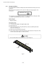
Cleaning Procedure
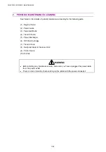
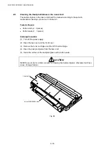
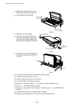
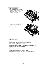
(1) Turn off the power supply, and unplug the power cable.
(2) Open the top cover.
(3) Remove the fusing unit from the printer and then remove the oil bottle and the fuser
cleaner form the fusing unit.
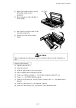
(4) Remove the oil pan unit from the fusing unit.
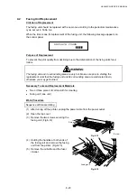
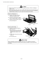
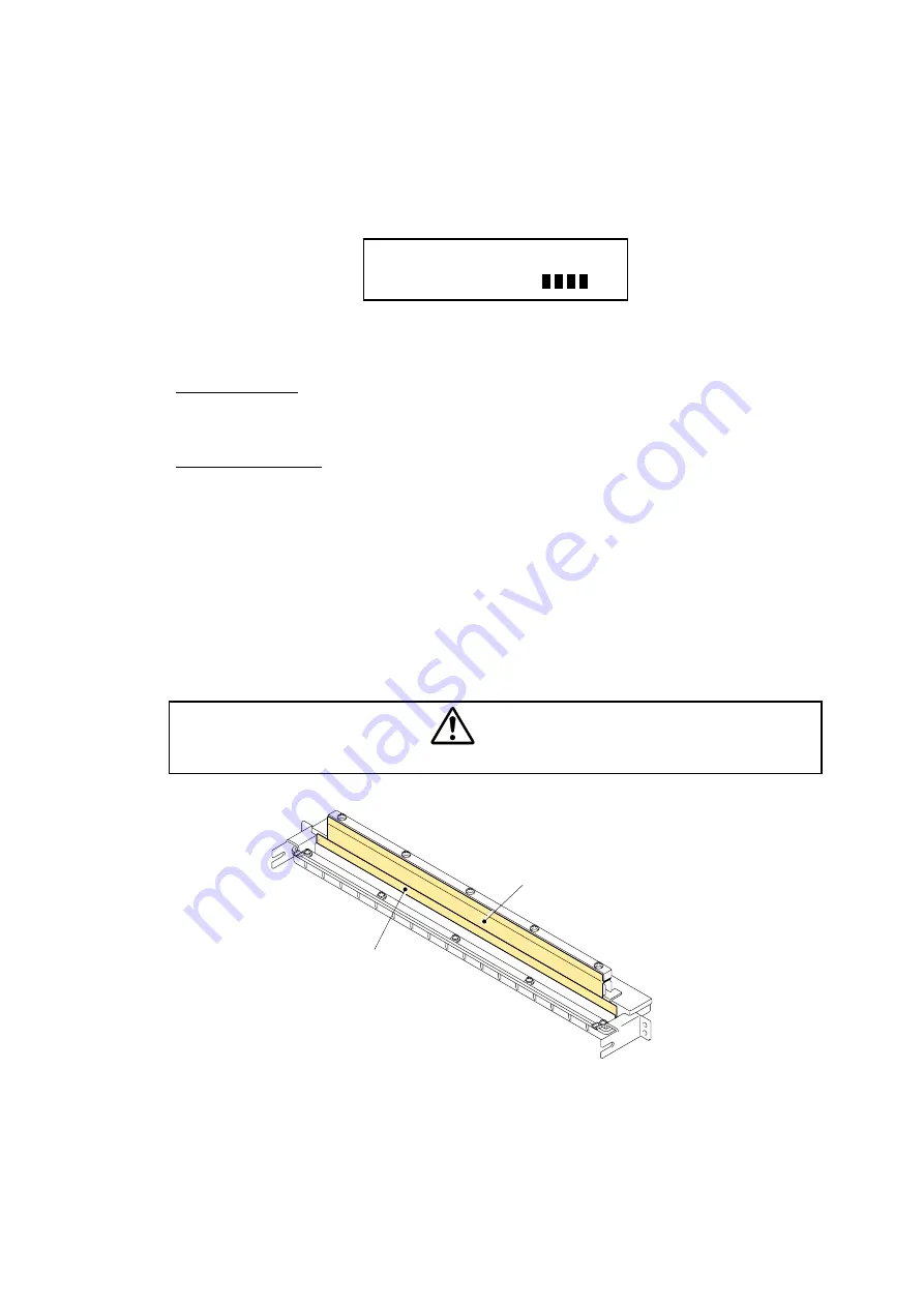
(5) Scour off toner scattered on the white felt surface of the oil pad and on the surface of the
oil blade using the head edge of a slotted screwdriver.
CAUTION
x
Do not scrub the felt too hard, otherwise it may cause damage to it.
Fig. 6-11
White felt
Oil blade
Содержание HL-3450CN Series
Страница 15: ...HL 3450CN SERVICE MANUAL xiii 3 Rating Label For US For Europe 4 Operation Label 5 Jam Label ...
Страница 17: ...HL 3450CN SERVICE MANUAL CHAPTER 1 PRODUCT OUTLINE ...
Страница 27: ...HL 3450CN SERVICE MANUAL CHAPTER 2 SPECIFICATIONS ...
Страница 39: ...CHAPTER 3 INSTALLATION ...
Страница 54: ...HL 3450CN SERVICE MANUAL CHAPTER 4 STRUCTURE OF SYSTEM COMPONENTS ...
Страница 87: ...CHAPTER 4 STRUCTURE OF SYSTEM COMPONENTS 4 34 Layout of Clutches 2 9 1 3 7 6 5 4 8 10 Fig 4 31 ...
Страница 104: ...HL 3450CN SERVICE MANUAL 4 51 Main PCB Circuit Diagram 1 8 CODE B512137CIR 1 8 LJ8907001 NAME ...
Страница 105: ...CHAPTER 4 STRUCTURE OF SYSTEM COMPONENTS 4 52 Main PCB Circuit Diagram 2 8 CODE B512137CIR 2 8 LJ8907001 NAME ...
Страница 106: ...HL 3450CN SERVICE MANUAL 4 53 Main PCB Circuit Diagram 3 8 CODE B512137CIR 3 8 LJ8907001 NAME ...
Страница 107: ...CHAPTER 4 STRUCTURE OF SYSTEM COMPONENTS 4 54 Main PCB Circuit Diagram 4 8 CODE B512137CIR 4 8 LJ8907001 NAME ...
Страница 108: ...HL 3450CN SERVICE MANUAL 4 55 Main PCB Circuit Diagram 5 8 CODE B512137CIR 5 8 LJ8907001 NAME ...
Страница 109: ...CHAPTER 4 STRUCTURE OF SYSTEM COMPONENTS 4 56 Main PCB Circuit Diagram 6 8 CODE B512137CIR 6 8 LJ8907001 NAME ...
Страница 110: ...HL 3450CN SERVICE MANUAL 4 57 Main PCB Circuit Diagram 7 8 CODE B512137CIR 7 8 LJ8907001 NAME ...
Страница 111: ...CHAPTER 4 STRUCTURE OF SYSTEM COMPONENTS 4 58 Main PCB Circuit Diagram 8 8 CODE B512137CIR 8 8 LJ8907001 NAME ...
Страница 112: ...HL 3450CN SERVICE MANUAL 4 59 Network Board PCB Circuit Diagram CODE LJ8107001 NAME B512058CIR ...
Страница 114: ...HL 3450CN SERVICE MANUAL 4 61 TAB2 HP TAB1 HN ACN4 ACN1 ACN3 ACN2 ACN5 Inlet Black White Power Switch Fig 4 40 ...
Страница 126: ...HL 3450CN SERVICE MANUAL CHAPTER 5 CONTROL PANEL OPERATION ...
Страница 173: ...HL 3450CN SERVICE MANUAL CHAPTER 6 PERIODIC MAINTENANCE ...
Страница 208: ...CHAPTER 7 DISASSEMBLY RE ASSEMBLY ...
Страница 264: ...HL 3450CN SERVICE MANUAL CHAPTER 8 TROUBLESHOOTING ...
Страница 310: ...HL 3450CN SERVICE MANUAL 8 47 5 IMAGE FAILURE 1 2 3 4 5 6 7 8 9 a 9 b 10 11 12 13 14 ...
Страница 311: ...CHAPTER 8 TROUBLESHOOTING 8 48 15 a 15 b 16 17 18 19 20 21 22 23 24 25 26 27 28 244m m 29 ...

