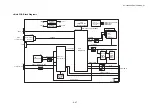
HL-3450CN SERVICE MANUAL
4-49
(5) DIMM
block
DIMM (Dual-Inline-Memory-Module) allows memory extension by up to 128MB in each
socket. 3 DIMM sockets are available.
The following type of DIMM can be installed into each slot.
x
Appearance:
100-pin
x
Memory type:
SDRAM
x
Access time:
66MHz or more, CL=2
x
Parity:
either Parity or Non-parity can be used
x
Memory capacity: 16MB, 32MB, 64MB, 128MB
<Recommended DIMM type>
<US>
x
16 Megabytes
TECHWORKS 12456-0001
x
32 Megabytes
TECHWORKS 12457-0001
x
64 Megabytes
TECHWORKS 12458-0001
x
128 Megabytes
TECHWORKS 12459-0001
<Europe>
x
16 Megabytes
BUFFALO TECHNOLOGY
12323-0001
x
32 Megabytes
BUFFALO TECHNOLOGY
12324-0001
x
64 Megabytes
BUFFALO TECHNOLOGY
12325-0001
x
128 Megabytes
BUFFALO TECHNOLOGY
12326-0001
Any combination of DIMM size can be installed into any slot in any order.
(6)
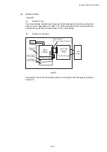
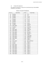
External interface block
x
Centronics Interface
x
Universal Serial Bus (USB)
x
Compact Flash
x
Ethernet 10/100 Base-TX
x
IDE Interface
(7)
Engine interface block
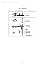
The engine interface consists of the following signals;
<IREADY>
The signal indicating the engine is ready
<PRREQ>
Signal requesting printing from the controller
<KEY_STATUS>
Signal indicating that a key switch status on the control panel has changed.
<VSYNC>
Vertical synchronization signal for printing
<HSYNC>
Horizontal synchronization signal for printing
<VIDEO>
Video data signal
<COMMAND>
Command signal sent from the controller to the engine
<STATUS>
Status signal sent from the engine to the controller
Содержание HL-3450CN Series
Страница 15: ...HL 3450CN SERVICE MANUAL xiii 3 Rating Label For US For Europe 4 Operation Label 5 Jam Label ...
Страница 17: ...HL 3450CN SERVICE MANUAL CHAPTER 1 PRODUCT OUTLINE ...
Страница 27: ...HL 3450CN SERVICE MANUAL CHAPTER 2 SPECIFICATIONS ...
Страница 39: ...CHAPTER 3 INSTALLATION ...
Страница 54: ...HL 3450CN SERVICE MANUAL CHAPTER 4 STRUCTURE OF SYSTEM COMPONENTS ...
Страница 87: ...CHAPTER 4 STRUCTURE OF SYSTEM COMPONENTS 4 34 Layout of Clutches 2 9 1 3 7 6 5 4 8 10 Fig 4 31 ...
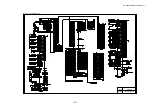
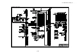
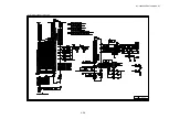
Страница 104: ...HL 3450CN SERVICE MANUAL 4 51 Main PCB Circuit Diagram 1 8 CODE B512137CIR 1 8 LJ8907001 NAME ...
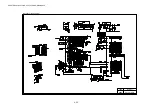
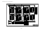
Страница 105: ...CHAPTER 4 STRUCTURE OF SYSTEM COMPONENTS 4 52 Main PCB Circuit Diagram 2 8 CODE B512137CIR 2 8 LJ8907001 NAME ...
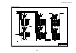
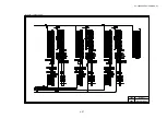
Страница 106: ...HL 3450CN SERVICE MANUAL 4 53 Main PCB Circuit Diagram 3 8 CODE B512137CIR 3 8 LJ8907001 NAME ...
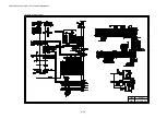
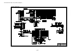
Страница 107: ...CHAPTER 4 STRUCTURE OF SYSTEM COMPONENTS 4 54 Main PCB Circuit Diagram 4 8 CODE B512137CIR 4 8 LJ8907001 NAME ...
Страница 108: ...HL 3450CN SERVICE MANUAL 4 55 Main PCB Circuit Diagram 5 8 CODE B512137CIR 5 8 LJ8907001 NAME ...
Страница 109: ...CHAPTER 4 STRUCTURE OF SYSTEM COMPONENTS 4 56 Main PCB Circuit Diagram 6 8 CODE B512137CIR 6 8 LJ8907001 NAME ...
Страница 110: ...HL 3450CN SERVICE MANUAL 4 57 Main PCB Circuit Diagram 7 8 CODE B512137CIR 7 8 LJ8907001 NAME ...
Страница 111: ...CHAPTER 4 STRUCTURE OF SYSTEM COMPONENTS 4 58 Main PCB Circuit Diagram 8 8 CODE B512137CIR 8 8 LJ8907001 NAME ...
Страница 112: ...HL 3450CN SERVICE MANUAL 4 59 Network Board PCB Circuit Diagram CODE LJ8107001 NAME B512058CIR ...
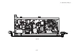
Страница 114: ...HL 3450CN SERVICE MANUAL 4 61 TAB2 HP TAB1 HN ACN4 ACN1 ACN3 ACN2 ACN5 Inlet Black White Power Switch Fig 4 40 ...
Страница 126: ...HL 3450CN SERVICE MANUAL CHAPTER 5 CONTROL PANEL OPERATION ...
Страница 173: ...HL 3450CN SERVICE MANUAL CHAPTER 6 PERIODIC MAINTENANCE ...
Страница 208: ...CHAPTER 7 DISASSEMBLY RE ASSEMBLY ...
Страница 264: ...HL 3450CN SERVICE MANUAL CHAPTER 8 TROUBLESHOOTING ...
Страница 310: ...HL 3450CN SERVICE MANUAL 8 47 5 IMAGE FAILURE 1 2 3 4 5 6 7 8 9 a 9 b 10 11 12 13 14 ...
Страница 311: ...CHAPTER 8 TROUBLESHOOTING 8 48 15 a 15 b 16 17 18 19 20 21 22 23 24 25 26 27 28 244m m 29 ...

