CHAPTER 5 CONTROL PANEL OPERATION
5-16
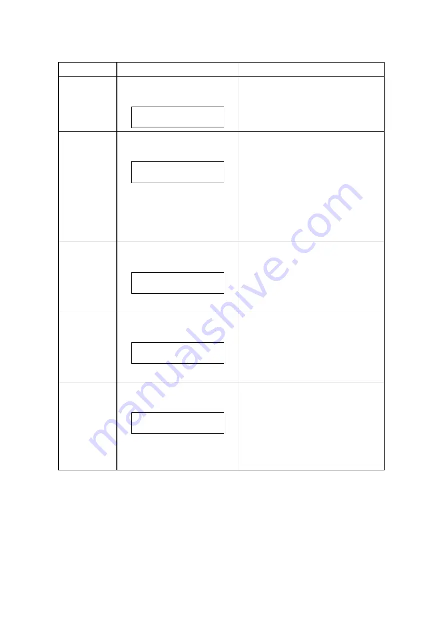
Code No.
LCD Message
Description of Message
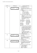
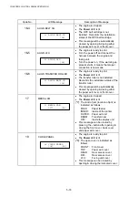
12-2
STACKER FULL
12 STACKER FULL
[*4]
x
The engine is ready to print.
x
The Power LED is lit.
x
Remove the paper on the stacker
(paper exit tray), then press the -
button.
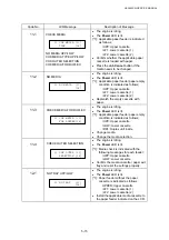
13
REPLACE TONER
13 REPLACE [*5]
TONER [*4]
Display of [4]:
C:YT Y toner cartridge
C:CT: C toner cartridge
C:MT M toner cartridge
C:KT K toner cartridge
x
The engine is ready to print.
x
The Power LED is lit.
[*5]: The toner empty condition is
indicated by the color code as
follows;
Y:
Yellow
M:
Magenta
C:
Cyan
K:
Black
x
Replace the indicated toner cartridge
with a new one of the correct color.
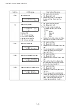
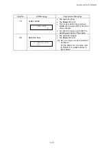
14-1
CHECK FUSER OIL
14 CHECK
FUSER OIL[*F0]
x
The engine is idling.
x
The Power LED is lit.
x
Replace the fuser oil bottle with a new
one.
x
This message will be automatically
cleared by opening & closing the
paper exit cover.
14-2
CHECK CLEANING ROLLER
14 CHECK CLEANING
ROLLER[*4][*FC]
x
The engine is idling.
x
The Power LED is lit.
x
Replace the fuser cleaner with a new
one.
x
Execute the Clear Care Mode after
the replacement of the fuser cleaner
to clear the Care Code [FC].
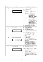
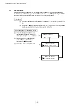
14-3
CHECK WASTE TONER PACK
14 CHECK WASTE
TONER PACK[*4]
x
The engine is idling.
x
The Power LED is lit.
x
Replace the waste toner pack with a
new one.
x
This message will be automatically
cleared by opening & closing the front
cover while replacing the waste toner
pack. The message can also be
cleared by pressing the - button.
Содержание HL-3450CN Series
Страница 15: ...HL 3450CN SERVICE MANUAL xiii 3 Rating Label For US For Europe 4 Operation Label 5 Jam Label ...
Страница 17: ...HL 3450CN SERVICE MANUAL CHAPTER 1 PRODUCT OUTLINE ...
Страница 27: ...HL 3450CN SERVICE MANUAL CHAPTER 2 SPECIFICATIONS ...
Страница 39: ...CHAPTER 3 INSTALLATION ...
Страница 54: ...HL 3450CN SERVICE MANUAL CHAPTER 4 STRUCTURE OF SYSTEM COMPONENTS ...
Страница 87: ...CHAPTER 4 STRUCTURE OF SYSTEM COMPONENTS 4 34 Layout of Clutches 2 9 1 3 7 6 5 4 8 10 Fig 4 31 ...
Страница 104: ...HL 3450CN SERVICE MANUAL 4 51 Main PCB Circuit Diagram 1 8 CODE B512137CIR 1 8 LJ8907001 NAME ...
Страница 105: ...CHAPTER 4 STRUCTURE OF SYSTEM COMPONENTS 4 52 Main PCB Circuit Diagram 2 8 CODE B512137CIR 2 8 LJ8907001 NAME ...
Страница 106: ...HL 3450CN SERVICE MANUAL 4 53 Main PCB Circuit Diagram 3 8 CODE B512137CIR 3 8 LJ8907001 NAME ...
Страница 107: ...CHAPTER 4 STRUCTURE OF SYSTEM COMPONENTS 4 54 Main PCB Circuit Diagram 4 8 CODE B512137CIR 4 8 LJ8907001 NAME ...
Страница 108: ...HL 3450CN SERVICE MANUAL 4 55 Main PCB Circuit Diagram 5 8 CODE B512137CIR 5 8 LJ8907001 NAME ...
Страница 109: ...CHAPTER 4 STRUCTURE OF SYSTEM COMPONENTS 4 56 Main PCB Circuit Diagram 6 8 CODE B512137CIR 6 8 LJ8907001 NAME ...
Страница 110: ...HL 3450CN SERVICE MANUAL 4 57 Main PCB Circuit Diagram 7 8 CODE B512137CIR 7 8 LJ8907001 NAME ...
Страница 111: ...CHAPTER 4 STRUCTURE OF SYSTEM COMPONENTS 4 58 Main PCB Circuit Diagram 8 8 CODE B512137CIR 8 8 LJ8907001 NAME ...
Страница 112: ...HL 3450CN SERVICE MANUAL 4 59 Network Board PCB Circuit Diagram CODE LJ8107001 NAME B512058CIR ...
Страница 114: ...HL 3450CN SERVICE MANUAL 4 61 TAB2 HP TAB1 HN ACN4 ACN1 ACN3 ACN2 ACN5 Inlet Black White Power Switch Fig 4 40 ...
Страница 126: ...HL 3450CN SERVICE MANUAL CHAPTER 5 CONTROL PANEL OPERATION ...
Страница 173: ...HL 3450CN SERVICE MANUAL CHAPTER 6 PERIODIC MAINTENANCE ...
Страница 208: ...CHAPTER 7 DISASSEMBLY RE ASSEMBLY ...
Страница 264: ...HL 3450CN SERVICE MANUAL CHAPTER 8 TROUBLESHOOTING ...
Страница 310: ...HL 3450CN SERVICE MANUAL 8 47 5 IMAGE FAILURE 1 2 3 4 5 6 7 8 9 a 9 b 10 11 12 13 14 ...
Страница 311: ...CHAPTER 8 TROUBLESHOOTING 8 48 15 a 15 b 16 17 18 19 20 21 22 23 24 25 26 27 28 244m m 29 ...

