HL-3450CN SERVICE MANUAL
5-5
2.2
Line Test Mode
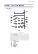
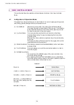
This mode tests the following items;
Item Self-test
Description
LCD TEST
Displays the checker pattern
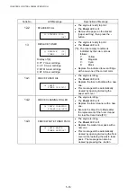
LED TEST
Checks that all LEDs are on / off.
SW TEST
Checks that all buttons work correctly.
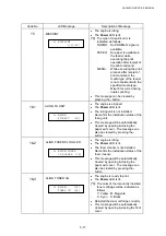
SENSOR TEST
Checks that all sensors work correctly.
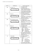
RAM SIZE TEST
Displays the NVRAM size
TRAY 1 CHECK
Displays the paper size of the upper cassette
(Tray 1).
TRAY 2 CHECK
Displays the paper size of the lower cassette
(Tray 2).
FLASH CARD-R/W TEST
Checks the compact flash card.
<Procedure>
NOTE:
x
It is possible to skip the test and proceed with the next test by pressing the Go
button.
x
If any errors occur during the following procedures, an error message appears on
the LCD. By pressing the Go button, it is possible to proceed with the test.
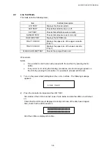
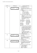
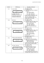
1)
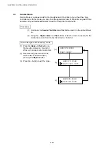
Turn on the power while holding down the + and – buttons. The following message
appears.
LINE TEST
2)
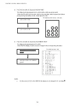
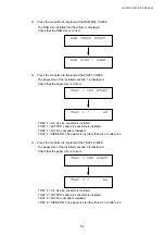
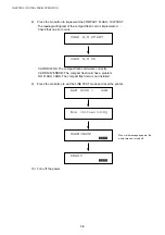
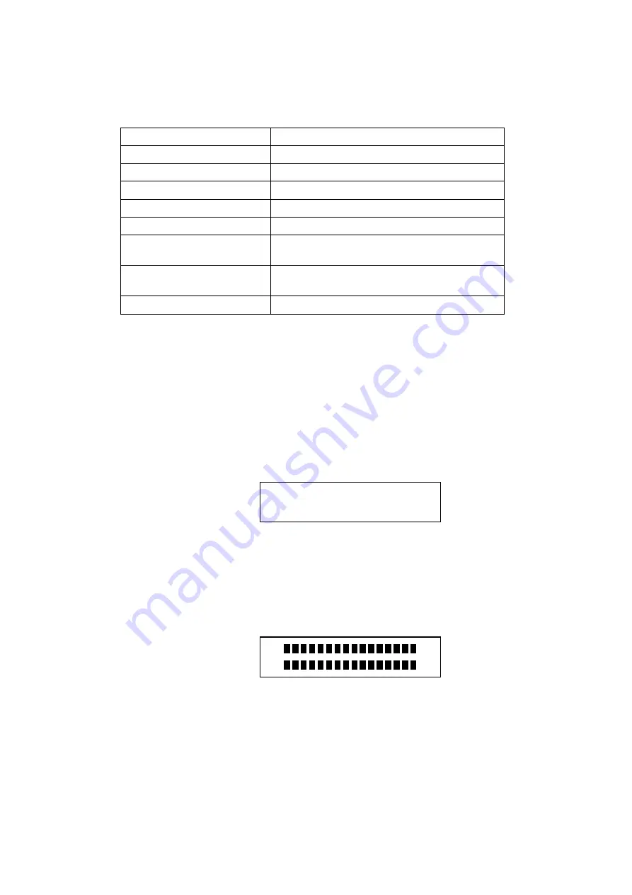
Press the Go button to implement the LCD TEST.
All columns of the LCD are turned on as shown below and also the LEDs are all turned
on.
Check that the LCDs are all displayed correctly and none of the dots have dropped.
Also, check that the LEDs are all on.
All of the LCDs are displayed at a time.
Содержание HL-3450CN Series
Страница 15: ...HL 3450CN SERVICE MANUAL xiii 3 Rating Label For US For Europe 4 Operation Label 5 Jam Label ...
Страница 17: ...HL 3450CN SERVICE MANUAL CHAPTER 1 PRODUCT OUTLINE ...
Страница 27: ...HL 3450CN SERVICE MANUAL CHAPTER 2 SPECIFICATIONS ...
Страница 39: ...CHAPTER 3 INSTALLATION ...
Страница 54: ...HL 3450CN SERVICE MANUAL CHAPTER 4 STRUCTURE OF SYSTEM COMPONENTS ...
Страница 87: ...CHAPTER 4 STRUCTURE OF SYSTEM COMPONENTS 4 34 Layout of Clutches 2 9 1 3 7 6 5 4 8 10 Fig 4 31 ...
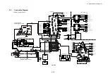
Страница 104: ...HL 3450CN SERVICE MANUAL 4 51 Main PCB Circuit Diagram 1 8 CODE B512137CIR 1 8 LJ8907001 NAME ...
Страница 105: ...CHAPTER 4 STRUCTURE OF SYSTEM COMPONENTS 4 52 Main PCB Circuit Diagram 2 8 CODE B512137CIR 2 8 LJ8907001 NAME ...
Страница 106: ...HL 3450CN SERVICE MANUAL 4 53 Main PCB Circuit Diagram 3 8 CODE B512137CIR 3 8 LJ8907001 NAME ...
Страница 107: ...CHAPTER 4 STRUCTURE OF SYSTEM COMPONENTS 4 54 Main PCB Circuit Diagram 4 8 CODE B512137CIR 4 8 LJ8907001 NAME ...
Страница 108: ...HL 3450CN SERVICE MANUAL 4 55 Main PCB Circuit Diagram 5 8 CODE B512137CIR 5 8 LJ8907001 NAME ...
Страница 109: ...CHAPTER 4 STRUCTURE OF SYSTEM COMPONENTS 4 56 Main PCB Circuit Diagram 6 8 CODE B512137CIR 6 8 LJ8907001 NAME ...
Страница 110: ...HL 3450CN SERVICE MANUAL 4 57 Main PCB Circuit Diagram 7 8 CODE B512137CIR 7 8 LJ8907001 NAME ...
Страница 111: ...CHAPTER 4 STRUCTURE OF SYSTEM COMPONENTS 4 58 Main PCB Circuit Diagram 8 8 CODE B512137CIR 8 8 LJ8907001 NAME ...
Страница 112: ...HL 3450CN SERVICE MANUAL 4 59 Network Board PCB Circuit Diagram CODE LJ8107001 NAME B512058CIR ...
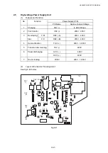
Страница 114: ...HL 3450CN SERVICE MANUAL 4 61 TAB2 HP TAB1 HN ACN4 ACN1 ACN3 ACN2 ACN5 Inlet Black White Power Switch Fig 4 40 ...
Страница 126: ...HL 3450CN SERVICE MANUAL CHAPTER 5 CONTROL PANEL OPERATION ...
Страница 173: ...HL 3450CN SERVICE MANUAL CHAPTER 6 PERIODIC MAINTENANCE ...
Страница 208: ...CHAPTER 7 DISASSEMBLY RE ASSEMBLY ...
Страница 264: ...HL 3450CN SERVICE MANUAL CHAPTER 8 TROUBLESHOOTING ...
Страница 310: ...HL 3450CN SERVICE MANUAL 8 47 5 IMAGE FAILURE 1 2 3 4 5 6 7 8 9 a 9 b 10 11 12 13 14 ...
Страница 311: ...CHAPTER 8 TROUBLESHOOTING 8 48 15 a 15 b 16 17 18 19 20 21 22 23 24 25 26 27 28 244m m 29 ...

