HL-3450CN SERVICE MANUAL
A-13
6)
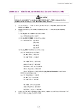
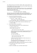
Re-enter the FU UNIT (NC8) value as follows;
i) Enter the value of NC8 - LP8 into the TOTAL PAGE counter.
(i.e.) NC8 - LP8 = 39,684 - 70,000 = - 30,316
Since the above result is minus, reduce the value of LP8 is 30,000P in order to
make the result plus, then enter it into the LIFE PERIOD SET counter in
FACTORY MODE.
The formula is as follows;
NC8 - LP8 = 39,684 - 30,000 = 9,684
Enter the value ‘9,684’ in TOTAL PAGE.
ii) Perform CLEAR CARE 8. (Refer to ‘36 CLEAR CARE’ in page V-24 of Chapter V.)
iii) Check that the value of NEXT CARE is reset correctly.
(i.e.) NC8 = 39,684P
iv) Reset the LIFE PERIOD counter in FACTORY MODE to 60,100.
7)
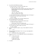
Re-enter the 240K KIT (NC10) value as follows;
i) Enter the value of NC10 - LP10 into the TOTAL PAGE counter.
(i.e.) NC9 - LP9 = 120,000 - 120,000 = 0
Enter the value ‘0’ into the TOTAL PAGE counter.
ii) Perform CLEAR CARE 9. (Refer to ‘36 CLEAR CARE’ in page V-24 of Chapter V.)
iii) Check that the value of NEXT CARE is reset correctly.
(i.e.) NC10 = 120,000P
8)
Re-enter the original TOTAL PAGE (T) value in TOTAL PAGE SET in FACTORY
MODE.
(i.e.)
T = 412P
9)
Re-enter the original EACH IMAGE (IY, IM, IC, IK) values in EACH IMAGE SET in
FACTORY MODE.
(i.e.)
(IY)=348P, (IM)=353P, (IC)=365P, (IK)=439P
10)
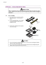
Ensure that the values in the LIFE PERIOD SET counters in FACTORY MODE are
correct.
(i.e.)
FC ROLL (LP2)=12,000P
BL UNIT (LP7)=50,000P
FU UNIT (LP8)=60,100P
120K KIT (LP10)=120,000P
11) Completed.
Содержание HL-3450CN Series
Страница 15: ...HL 3450CN SERVICE MANUAL xiii 3 Rating Label For US For Europe 4 Operation Label 5 Jam Label ...
Страница 17: ...HL 3450CN SERVICE MANUAL CHAPTER 1 PRODUCT OUTLINE ...
Страница 27: ...HL 3450CN SERVICE MANUAL CHAPTER 2 SPECIFICATIONS ...
Страница 39: ...CHAPTER 3 INSTALLATION ...
Страница 54: ...HL 3450CN SERVICE MANUAL CHAPTER 4 STRUCTURE OF SYSTEM COMPONENTS ...
Страница 87: ...CHAPTER 4 STRUCTURE OF SYSTEM COMPONENTS 4 34 Layout of Clutches 2 9 1 3 7 6 5 4 8 10 Fig 4 31 ...
Страница 104: ...HL 3450CN SERVICE MANUAL 4 51 Main PCB Circuit Diagram 1 8 CODE B512137CIR 1 8 LJ8907001 NAME ...
Страница 105: ...CHAPTER 4 STRUCTURE OF SYSTEM COMPONENTS 4 52 Main PCB Circuit Diagram 2 8 CODE B512137CIR 2 8 LJ8907001 NAME ...
Страница 106: ...HL 3450CN SERVICE MANUAL 4 53 Main PCB Circuit Diagram 3 8 CODE B512137CIR 3 8 LJ8907001 NAME ...
Страница 107: ...CHAPTER 4 STRUCTURE OF SYSTEM COMPONENTS 4 54 Main PCB Circuit Diagram 4 8 CODE B512137CIR 4 8 LJ8907001 NAME ...
Страница 108: ...HL 3450CN SERVICE MANUAL 4 55 Main PCB Circuit Diagram 5 8 CODE B512137CIR 5 8 LJ8907001 NAME ...
Страница 109: ...CHAPTER 4 STRUCTURE OF SYSTEM COMPONENTS 4 56 Main PCB Circuit Diagram 6 8 CODE B512137CIR 6 8 LJ8907001 NAME ...
Страница 110: ...HL 3450CN SERVICE MANUAL 4 57 Main PCB Circuit Diagram 7 8 CODE B512137CIR 7 8 LJ8907001 NAME ...
Страница 111: ...CHAPTER 4 STRUCTURE OF SYSTEM COMPONENTS 4 58 Main PCB Circuit Diagram 8 8 CODE B512137CIR 8 8 LJ8907001 NAME ...
Страница 112: ...HL 3450CN SERVICE MANUAL 4 59 Network Board PCB Circuit Diagram CODE LJ8107001 NAME B512058CIR ...
Страница 114: ...HL 3450CN SERVICE MANUAL 4 61 TAB2 HP TAB1 HN ACN4 ACN1 ACN3 ACN2 ACN5 Inlet Black White Power Switch Fig 4 40 ...
Страница 126: ...HL 3450CN SERVICE MANUAL CHAPTER 5 CONTROL PANEL OPERATION ...
Страница 173: ...HL 3450CN SERVICE MANUAL CHAPTER 6 PERIODIC MAINTENANCE ...
Страница 208: ...CHAPTER 7 DISASSEMBLY RE ASSEMBLY ...
Страница 264: ...HL 3450CN SERVICE MANUAL CHAPTER 8 TROUBLESHOOTING ...
Страница 310: ...HL 3450CN SERVICE MANUAL 8 47 5 IMAGE FAILURE 1 2 3 4 5 6 7 8 9 a 9 b 10 11 12 13 14 ...
Страница 311: ...CHAPTER 8 TROUBLESHOOTING 8 48 15 a 15 b 16 17 18 19 20 21 22 23 24 25 26 27 28 244m m 29 ...

