HL-3450CN SERVICE MANUAL
1-9
4. DESCRIPTION OF CONTROL PANEL
The printer control panel provides control of the printer including test printing, maintenance
operations performed by the video controller and also the ones which are performed by the
engine controller.
The Video Controller Mode and the Engine Controller Mode have some common functions.
Under normal circumstances the functions in the Video controller mode will be used. Refer to
CHAPTER 5 for further information.
4.1
Video Controller Mode
The printer goes into the Video Controller Mode when the power is turned on by pressing the
power button.
The Video Controller Mode supplies the general test printing and setting functions and some
of the maintenance operations. If further engine settings are required, use the Engine
Controller Mode.
4.2
Engine Controller Mode
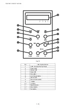
The printer goes into the Engine Controller Mode when power is turned on by pressing the
power button at the same time as holding down the Secure print, Back and Set buttons.
(Refer to Fig.1-4.)
NOTE:
This mode provides unique control panel display and operation functions which are
completely different from the ones described on the actual control panel labels or in the
user’s guide. Refer to CHAPTER 5 for detailed information.
Содержание HL-3450CN Series
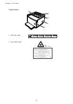
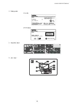
Страница 15: ...HL 3450CN SERVICE MANUAL xiii 3 Rating Label For US For Europe 4 Operation Label 5 Jam Label ...
Страница 17: ...HL 3450CN SERVICE MANUAL CHAPTER 1 PRODUCT OUTLINE ...
Страница 27: ...HL 3450CN SERVICE MANUAL CHAPTER 2 SPECIFICATIONS ...
Страница 39: ...CHAPTER 3 INSTALLATION ...
Страница 54: ...HL 3450CN SERVICE MANUAL CHAPTER 4 STRUCTURE OF SYSTEM COMPONENTS ...
Страница 87: ...CHAPTER 4 STRUCTURE OF SYSTEM COMPONENTS 4 34 Layout of Clutches 2 9 1 3 7 6 5 4 8 10 Fig 4 31 ...
Страница 104: ...HL 3450CN SERVICE MANUAL 4 51 Main PCB Circuit Diagram 1 8 CODE B512137CIR 1 8 LJ8907001 NAME ...
Страница 105: ...CHAPTER 4 STRUCTURE OF SYSTEM COMPONENTS 4 52 Main PCB Circuit Diagram 2 8 CODE B512137CIR 2 8 LJ8907001 NAME ...
Страница 106: ...HL 3450CN SERVICE MANUAL 4 53 Main PCB Circuit Diagram 3 8 CODE B512137CIR 3 8 LJ8907001 NAME ...
Страница 107: ...CHAPTER 4 STRUCTURE OF SYSTEM COMPONENTS 4 54 Main PCB Circuit Diagram 4 8 CODE B512137CIR 4 8 LJ8907001 NAME ...
Страница 108: ...HL 3450CN SERVICE MANUAL 4 55 Main PCB Circuit Diagram 5 8 CODE B512137CIR 5 8 LJ8907001 NAME ...
Страница 109: ...CHAPTER 4 STRUCTURE OF SYSTEM COMPONENTS 4 56 Main PCB Circuit Diagram 6 8 CODE B512137CIR 6 8 LJ8907001 NAME ...
Страница 110: ...HL 3450CN SERVICE MANUAL 4 57 Main PCB Circuit Diagram 7 8 CODE B512137CIR 7 8 LJ8907001 NAME ...
Страница 111: ...CHAPTER 4 STRUCTURE OF SYSTEM COMPONENTS 4 58 Main PCB Circuit Diagram 8 8 CODE B512137CIR 8 8 LJ8907001 NAME ...
Страница 112: ...HL 3450CN SERVICE MANUAL 4 59 Network Board PCB Circuit Diagram CODE LJ8107001 NAME B512058CIR ...
Страница 114: ...HL 3450CN SERVICE MANUAL 4 61 TAB2 HP TAB1 HN ACN4 ACN1 ACN3 ACN2 ACN5 Inlet Black White Power Switch Fig 4 40 ...
Страница 126: ...HL 3450CN SERVICE MANUAL CHAPTER 5 CONTROL PANEL OPERATION ...
Страница 173: ...HL 3450CN SERVICE MANUAL CHAPTER 6 PERIODIC MAINTENANCE ...
Страница 208: ...CHAPTER 7 DISASSEMBLY RE ASSEMBLY ...
Страница 264: ...HL 3450CN SERVICE MANUAL CHAPTER 8 TROUBLESHOOTING ...
Страница 310: ...HL 3450CN SERVICE MANUAL 8 47 5 IMAGE FAILURE 1 2 3 4 5 6 7 8 9 a 9 b 10 11 12 13 14 ...
Страница 311: ...CHAPTER 8 TROUBLESHOOTING 8 48 15 a 15 b 16 17 18 19 20 21 22 23 24 25 26 27 28 244m m 29 ...

