HL-3450CN SERVICE MANUAL
6-19
3. PERIODIC MAINTENANCE PARTS
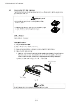
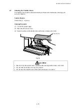
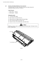
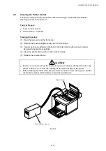
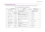
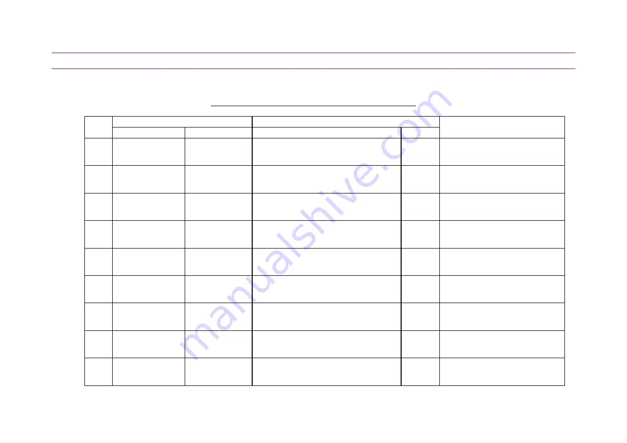
Maintenance Work should be implemented according to the “Periodic Maintenance Parts and Maintenance Cycle” set out in Table 6-4.
Table 6-4: Periodic Maintenance Parts and Maintenance Cycle
No.
Maintenance Parts
Description
Replacement Cycle *1
Parts Name
No.
Function
Section
(Condition or Case)
1
OPC Belt Cartridge
Accessory
Consists of the OPC belt and forms an
electrostatic latent image.
4.1
120K images or 12 months
whichever comes first.
2
Fusing Unit *2
LJ2322001 (US)
LJ2323001 (EC)
Fixes the toner image onto the transported
paper.
4.2 70K
prints
3
Transfer Roller *3
LJ2211001
Transfers the toner image from the
transfer drum onto the transported paper.
4.3 240K
prints
4
Paper Discharger
*4
LJ2212001
Separates paper from the transfer drum.
4.4 120K
prints
5
Drum Cleaner *3
LJ2214001
Cleans residual toner from the transfer
drum.
4.5 240K
prints
6
Ozone Filter E
LM0310001
Absorbs ozone.
4.6
Every 12 months
7
Paper Feeding Roller
Separator Pad *5
UH3485001
LJ2317001
Picks up sheets of paper one by one from
the media cassette.
4.7 120K
prints
8 Transfer
Drum
LJ2215001
Forms the toner image and transfers it
onto paper.
4.8 600K
images
9 Oil
Pad
LJ2329001
Cleans paper dust from the heat roller.
4.9 35K
prints
Содержание HL-3450CN Series
Страница 15: ...HL 3450CN SERVICE MANUAL xiii 3 Rating Label For US For Europe 4 Operation Label 5 Jam Label ...
Страница 17: ...HL 3450CN SERVICE MANUAL CHAPTER 1 PRODUCT OUTLINE ...
Страница 27: ...HL 3450CN SERVICE MANUAL CHAPTER 2 SPECIFICATIONS ...
Страница 39: ...CHAPTER 3 INSTALLATION ...
Страница 54: ...HL 3450CN SERVICE MANUAL CHAPTER 4 STRUCTURE OF SYSTEM COMPONENTS ...
Страница 87: ...CHAPTER 4 STRUCTURE OF SYSTEM COMPONENTS 4 34 Layout of Clutches 2 9 1 3 7 6 5 4 8 10 Fig 4 31 ...
Страница 104: ...HL 3450CN SERVICE MANUAL 4 51 Main PCB Circuit Diagram 1 8 CODE B512137CIR 1 8 LJ8907001 NAME ...
Страница 105: ...CHAPTER 4 STRUCTURE OF SYSTEM COMPONENTS 4 52 Main PCB Circuit Diagram 2 8 CODE B512137CIR 2 8 LJ8907001 NAME ...
Страница 106: ...HL 3450CN SERVICE MANUAL 4 53 Main PCB Circuit Diagram 3 8 CODE B512137CIR 3 8 LJ8907001 NAME ...
Страница 107: ...CHAPTER 4 STRUCTURE OF SYSTEM COMPONENTS 4 54 Main PCB Circuit Diagram 4 8 CODE B512137CIR 4 8 LJ8907001 NAME ...
Страница 108: ...HL 3450CN SERVICE MANUAL 4 55 Main PCB Circuit Diagram 5 8 CODE B512137CIR 5 8 LJ8907001 NAME ...
Страница 109: ...CHAPTER 4 STRUCTURE OF SYSTEM COMPONENTS 4 56 Main PCB Circuit Diagram 6 8 CODE B512137CIR 6 8 LJ8907001 NAME ...
Страница 110: ...HL 3450CN SERVICE MANUAL 4 57 Main PCB Circuit Diagram 7 8 CODE B512137CIR 7 8 LJ8907001 NAME ...
Страница 111: ...CHAPTER 4 STRUCTURE OF SYSTEM COMPONENTS 4 58 Main PCB Circuit Diagram 8 8 CODE B512137CIR 8 8 LJ8907001 NAME ...
Страница 112: ...HL 3450CN SERVICE MANUAL 4 59 Network Board PCB Circuit Diagram CODE LJ8107001 NAME B512058CIR ...
Страница 114: ...HL 3450CN SERVICE MANUAL 4 61 TAB2 HP TAB1 HN ACN4 ACN1 ACN3 ACN2 ACN5 Inlet Black White Power Switch Fig 4 40 ...
Страница 126: ...HL 3450CN SERVICE MANUAL CHAPTER 5 CONTROL PANEL OPERATION ...
Страница 173: ...HL 3450CN SERVICE MANUAL CHAPTER 6 PERIODIC MAINTENANCE ...
Страница 208: ...CHAPTER 7 DISASSEMBLY RE ASSEMBLY ...
Страница 264: ...HL 3450CN SERVICE MANUAL CHAPTER 8 TROUBLESHOOTING ...
Страница 310: ...HL 3450CN SERVICE MANUAL 8 47 5 IMAGE FAILURE 1 2 3 4 5 6 7 8 9 a 9 b 10 11 12 13 14 ...
Страница 311: ...CHAPTER 8 TROUBLESHOOTING 8 48 15 a 15 b 16 17 18 19 20 21 22 23 24 25 26 27 28 244m m 29 ...


