HL-3450CN SERVICE MANUAL
4-35
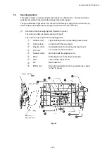
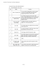
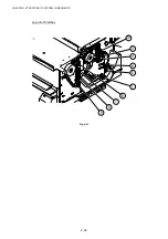
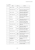
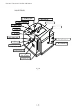
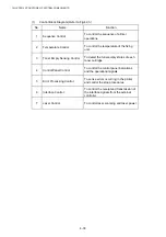
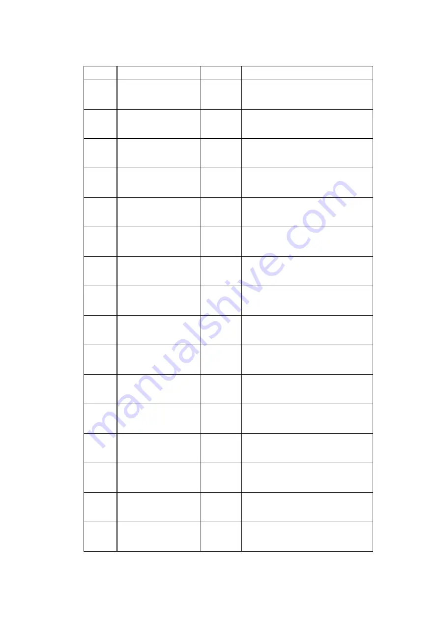
(4) Sensors
No. Name Code
Function
1
Paper size sensor
PSU
Photo sensor to detect the paper size.
2
Paper feeding sensor
PS 1
Photo sensor to detect when paper is
fed from the media cassette.
3
Paper exit sensor
PS 2
Photo sensor to detect that paper is
exited from the paper exit unit.
4
Paper empty sensor
PS 3
Photo sensor to detect if paper is
loaded in the media cassette.
5 Oil
sensor
OIL Photo sensor to detect if the fusing
unit oil is empty.
6 OHP
sensor
OHP Photo sensor to detect if media in the
media cassette is an OHP.
7
Drum jam sensor
DPJ
Photo sensor to detect if paper is
wound around the transfer drum.
8
Drum encoder sensor
PS 4
Photo sensor to detect rotation of the
transfer drum.
9 Belt
sensor
PBS Photo sensor to detect the home
position of the OPC belt.
10 Toner
sensor
TPD/TTR
Photo sensor to detect if the toner is
empty for each toner cartridge.
11
Waste toner sensor
WTS
Photo sensor to detect if the waste
toner bottle is full of toner.
12
Home position sensor
GHP1/
GHP2
Photo sensor to detect the position of
the toner cartridge.
13
Cleaning roller sensor
PS 5
Photo sensor to detect if the fuser
cleaner is fitted in the fixing unit.
14
Temperature sensor
for fusing unit
TH
Thermistor to detect the fuser
temperature.
15
Paper full sensor
PS 6
The sensor to detect when the paper
eject tray is full of paper.
16
Toner key sensor
TNK
The sensor to detect the key provided
in the toner cartridge.
Содержание HL-3450CN Series
Страница 15: ...HL 3450CN SERVICE MANUAL xiii 3 Rating Label For US For Europe 4 Operation Label 5 Jam Label ...
Страница 17: ...HL 3450CN SERVICE MANUAL CHAPTER 1 PRODUCT OUTLINE ...
Страница 27: ...HL 3450CN SERVICE MANUAL CHAPTER 2 SPECIFICATIONS ...
Страница 39: ...CHAPTER 3 INSTALLATION ...
Страница 54: ...HL 3450CN SERVICE MANUAL CHAPTER 4 STRUCTURE OF SYSTEM COMPONENTS ...
Страница 87: ...CHAPTER 4 STRUCTURE OF SYSTEM COMPONENTS 4 34 Layout of Clutches 2 9 1 3 7 6 5 4 8 10 Fig 4 31 ...
Страница 104: ...HL 3450CN SERVICE MANUAL 4 51 Main PCB Circuit Diagram 1 8 CODE B512137CIR 1 8 LJ8907001 NAME ...
Страница 105: ...CHAPTER 4 STRUCTURE OF SYSTEM COMPONENTS 4 52 Main PCB Circuit Diagram 2 8 CODE B512137CIR 2 8 LJ8907001 NAME ...
Страница 106: ...HL 3450CN SERVICE MANUAL 4 53 Main PCB Circuit Diagram 3 8 CODE B512137CIR 3 8 LJ8907001 NAME ...
Страница 107: ...CHAPTER 4 STRUCTURE OF SYSTEM COMPONENTS 4 54 Main PCB Circuit Diagram 4 8 CODE B512137CIR 4 8 LJ8907001 NAME ...
Страница 108: ...HL 3450CN SERVICE MANUAL 4 55 Main PCB Circuit Diagram 5 8 CODE B512137CIR 5 8 LJ8907001 NAME ...
Страница 109: ...CHAPTER 4 STRUCTURE OF SYSTEM COMPONENTS 4 56 Main PCB Circuit Diagram 6 8 CODE B512137CIR 6 8 LJ8907001 NAME ...
Страница 110: ...HL 3450CN SERVICE MANUAL 4 57 Main PCB Circuit Diagram 7 8 CODE B512137CIR 7 8 LJ8907001 NAME ...
Страница 111: ...CHAPTER 4 STRUCTURE OF SYSTEM COMPONENTS 4 58 Main PCB Circuit Diagram 8 8 CODE B512137CIR 8 8 LJ8907001 NAME ...
Страница 112: ...HL 3450CN SERVICE MANUAL 4 59 Network Board PCB Circuit Diagram CODE LJ8107001 NAME B512058CIR ...
Страница 114: ...HL 3450CN SERVICE MANUAL 4 61 TAB2 HP TAB1 HN ACN4 ACN1 ACN3 ACN2 ACN5 Inlet Black White Power Switch Fig 4 40 ...
Страница 126: ...HL 3450CN SERVICE MANUAL CHAPTER 5 CONTROL PANEL OPERATION ...
Страница 173: ...HL 3450CN SERVICE MANUAL CHAPTER 6 PERIODIC MAINTENANCE ...
Страница 208: ...CHAPTER 7 DISASSEMBLY RE ASSEMBLY ...
Страница 264: ...HL 3450CN SERVICE MANUAL CHAPTER 8 TROUBLESHOOTING ...
Страница 310: ...HL 3450CN SERVICE MANUAL 8 47 5 IMAGE FAILURE 1 2 3 4 5 6 7 8 9 a 9 b 10 11 12 13 14 ...
Страница 311: ...CHAPTER 8 TROUBLESHOOTING 8 48 15 a 15 b 16 17 18 19 20 21 22 23 24 25 26 27 28 244m m 29 ...

