CHAPTER 4 STRUCTURE OF SYSTEM COMPONENTS
4-22
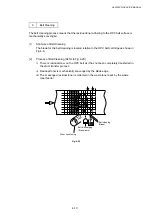
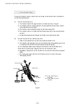
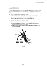
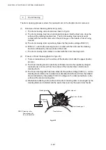
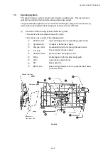
9 Drum
Cleaning
The drum cleaning process is where the residual toner on the transfer drum is removed.
(1)
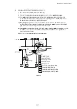
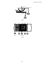
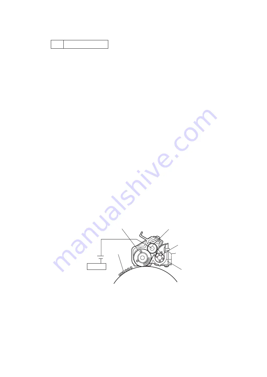
Structure of Drum Cleaning (Refer to Fig.4-23.)
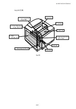
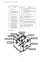
i) The drum cleaning unit is located as shown in Fig.4-8.
ii) The drum cleaning brush is a semiconductor type so that the brush can clean the
surface of the rotating transfer drum. The Drum cleaning brush is kept out of
contact with the transfer drum when the print image on the transfer drum is being
created.
iii) The drum cleaning roller is positively biased by the positive voltage FCBV (V).
iv) FCBV (V) is fed to the cleaning brush in contact with the roller and the cleaning
brush is self-biased by the resistance of the brush.
v) The drum cleaning roller rotates in contact with the drum cleaning brush.
(2)
Process of Drum Cleaning (Refer to Fig.4-23.)
i) There is residual toner on the surface of the transfer drum after the paper transfer
process.
ii) The Drum cleaning brush is positively self-biased and so the negatively charged
residual toner is removed from the surface of the transfer drum onto the drum
cleaning brush.
iii) The Drum cleaning roller has been biased to the positive voltage FCBV (V). As the
cleaning brush rotates, the residual toner absorbed into the brush from the transfer
drum is attracted by the positive FCBV (V) voltage on the roller and adheres to the
surface of the drum cleaning roller.
iv) Waste toner adhering to the surface of the drum cleaning roller is scavenged by the
cleaning blade and collected into the waste toner pack by the waste toner feeder.
FCBV
Fig. 4-23
FCBV: Cleaning roller
Power supply for
fuser cleaner bias
Transfer drum
Drum cleaner
West toner feeder
Drum cleaning unit
Cleaning brush
Residual
Toner
Содержание HL-3450CN Series
Страница 15: ...HL 3450CN SERVICE MANUAL xiii 3 Rating Label For US For Europe 4 Operation Label 5 Jam Label ...
Страница 17: ...HL 3450CN SERVICE MANUAL CHAPTER 1 PRODUCT OUTLINE ...
Страница 27: ...HL 3450CN SERVICE MANUAL CHAPTER 2 SPECIFICATIONS ...
Страница 39: ...CHAPTER 3 INSTALLATION ...
Страница 54: ...HL 3450CN SERVICE MANUAL CHAPTER 4 STRUCTURE OF SYSTEM COMPONENTS ...
Страница 87: ...CHAPTER 4 STRUCTURE OF SYSTEM COMPONENTS 4 34 Layout of Clutches 2 9 1 3 7 6 5 4 8 10 Fig 4 31 ...
Страница 104: ...HL 3450CN SERVICE MANUAL 4 51 Main PCB Circuit Diagram 1 8 CODE B512137CIR 1 8 LJ8907001 NAME ...
Страница 105: ...CHAPTER 4 STRUCTURE OF SYSTEM COMPONENTS 4 52 Main PCB Circuit Diagram 2 8 CODE B512137CIR 2 8 LJ8907001 NAME ...
Страница 106: ...HL 3450CN SERVICE MANUAL 4 53 Main PCB Circuit Diagram 3 8 CODE B512137CIR 3 8 LJ8907001 NAME ...
Страница 107: ...CHAPTER 4 STRUCTURE OF SYSTEM COMPONENTS 4 54 Main PCB Circuit Diagram 4 8 CODE B512137CIR 4 8 LJ8907001 NAME ...
Страница 108: ...HL 3450CN SERVICE MANUAL 4 55 Main PCB Circuit Diagram 5 8 CODE B512137CIR 5 8 LJ8907001 NAME ...
Страница 109: ...CHAPTER 4 STRUCTURE OF SYSTEM COMPONENTS 4 56 Main PCB Circuit Diagram 6 8 CODE B512137CIR 6 8 LJ8907001 NAME ...
Страница 110: ...HL 3450CN SERVICE MANUAL 4 57 Main PCB Circuit Diagram 7 8 CODE B512137CIR 7 8 LJ8907001 NAME ...
Страница 111: ...CHAPTER 4 STRUCTURE OF SYSTEM COMPONENTS 4 58 Main PCB Circuit Diagram 8 8 CODE B512137CIR 8 8 LJ8907001 NAME ...
Страница 112: ...HL 3450CN SERVICE MANUAL 4 59 Network Board PCB Circuit Diagram CODE LJ8107001 NAME B512058CIR ...
Страница 114: ...HL 3450CN SERVICE MANUAL 4 61 TAB2 HP TAB1 HN ACN4 ACN1 ACN3 ACN2 ACN5 Inlet Black White Power Switch Fig 4 40 ...
Страница 126: ...HL 3450CN SERVICE MANUAL CHAPTER 5 CONTROL PANEL OPERATION ...
Страница 173: ...HL 3450CN SERVICE MANUAL CHAPTER 6 PERIODIC MAINTENANCE ...
Страница 208: ...CHAPTER 7 DISASSEMBLY RE ASSEMBLY ...
Страница 264: ...HL 3450CN SERVICE MANUAL CHAPTER 8 TROUBLESHOOTING ...
Страница 310: ...HL 3450CN SERVICE MANUAL 8 47 5 IMAGE FAILURE 1 2 3 4 5 6 7 8 9 a 9 b 10 11 12 13 14 ...
Страница 311: ...CHAPTER 8 TROUBLESHOOTING 8 48 15 a 15 b 16 17 18 19 20 21 22 23 24 25 26 27 28 244m m 29 ...

