


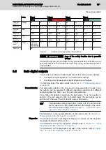
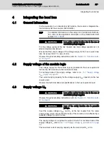
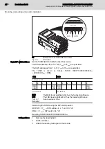

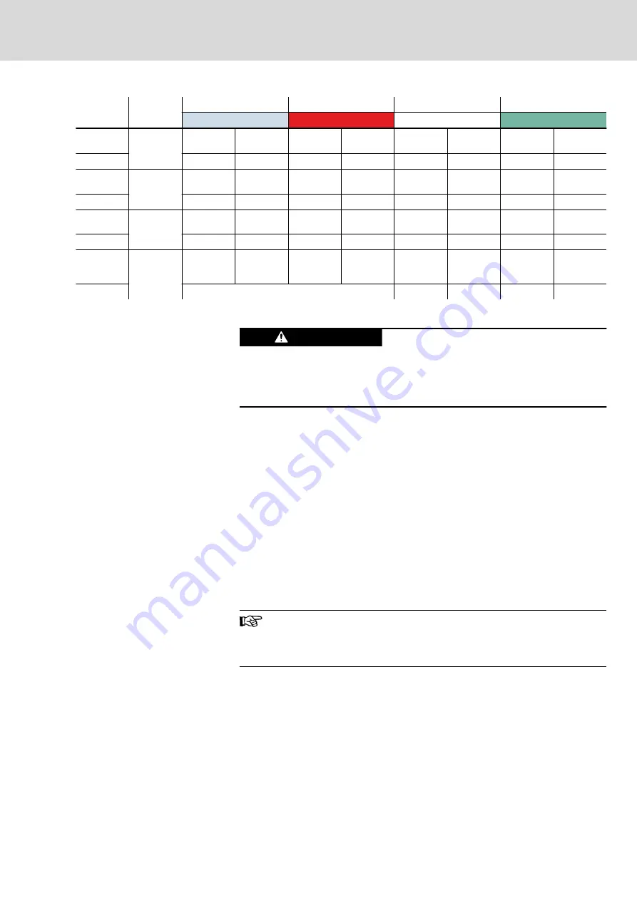
Color
Plug 1
Plug 2
Plug 3
Plug 4
(Blue)
(Red)
(White)
(Green)
Terminal
point
Orange
00
01
02
03
04
05
06
07
Function
OUT0_CH1 OUT0_CH2 OUT1_CH1 OUT1_CH2 OUT2_CH1 OUT2_CH2 OUT3_CH1 OUT3_CH2
Terminal
point
Blue
10
11
12
13
14
15
16
17
Function
GND
GND
GND
GND
GND
GND
GND
GND
Terminal
point
Blue
20
21
22
23
24
25
26
27
Function
GND
GND
GND
GND
GND
GND
GND
GND
Terminal
point
Green
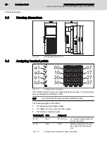
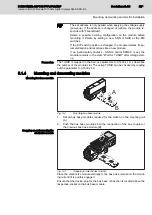
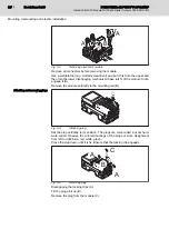
Attaching
and remov‐
ing 30 plugs
31
32
33
34
35
36
37
Function
FE
Tab. 3-2:
Terminal point assignment, I/O connection
Loss of the safety function due to parasitic
voltage
WARNING
Connect the ground of the actuator to the ground terminal point of the corre‐
sponding output on the IndraControl S20 plug. Using an external ground is
not permitted.
3.5
Safe digital outputs
The module is provided with safe digital outputs that can be used as follows:
●
For dual-channel assignment: Four dual-channel outputs
●
For single-channel assignment: Eight single-channel outputs
For technical data of the safe outputs, refer to
tab. 11-9 "Safe digital outputs"
Parameterization
The safe digital outputs of the module can be parameterized in pairs. Thus,
the outputs can be adjusted to different operating conditions and different
safety integrities SIL, SILCL, cat., PL can be implemented.
For a high error detection, switch-on the test pulses. If it is not possible to
switch on the test pulses for the connected loads, the test pulses can be
switched off. However, the error detection rate is then lower.
The attainable safety integrity (SIL, SILCL, cat., PL) and error de‐
tection depends on the parameterization, the design of the actua‐
tor and the cable routing, refer to
ples of the safe outputs" on page 33
.
For information on the parameterization of the outputs, refer to
"Parameterizing the safe outputs" on page 29
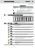
Diagnostics
It is diagnosed via the local diagnostic displays as well as via the diagnostic
messages transferred to the control.
For information on the local diagnostic displays, refer to
diagnostic and status displays" on page 15
For information on the diagnostic messages of the outputs, refer to
9.2.2 "Errors of the safe digital outputs" on page 48
.
DOK-CONTRL-S20*SSDO*8*-AP02-EN-P
Bosch Rexroth AG
13/85
IndraControl S20 Module With Safe Digital Outputs S20-SSDO-8/3
Product description


