

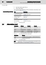

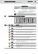
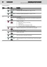
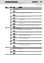
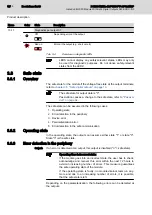


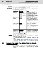


Name
Color
State
Description
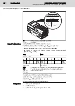
10-17
Diagnostics per output 0-7
Off
No pending error at the output.
Red on
RD RD
Error at the output (e.g. short circuit).
Tab. 3-4:
Overview on diagnostic LEDs
LEDS cannot display any safety-relevant states. LEDs may only
be used for diagnostic purposes. Do not derive safety-relevant
states from the LEDs!
3.8
Safe state
3.8.1
Overview
The safe state for the module if the voltage-free state at the output terminals,
refer to
chapter 3.5 "Safe digital outputs" on page 13
The safe state for output data is "0".
Passivation causes a change to the safe state, refer to
.
The safe state can be assumed in the following cases:
1. Operating state
2. Error detection in the periphery
3. Device error
4. Parameterization error
5. Error detection in the safe communication
3.8.2
Operating state
In the operating state, the outputs can assume either state "1" or state "0".
State "0" is the safe state.
3.8.3
Error detection in the periphery
Outputs
If an error is detected at an output, this output is disabled ("0" = safe state).
Operating time in incorrect state:
If the module goes into an incorrect state, the user has to check,
acknowledge and recover this error within the next 72 hours to
avoid an increasing number of errors. This measure guarantees
the safe operating state of the module.
If the operating state is faulty, no module-internal tests run any‐
more and due to an increasing number of errors, it is possible,
that the safe state is left.
Depending on the parameterization, the following errors can be detected at
the outputs:
Bosch Rexroth AG
DOK-CONTRL-S20*SSDO*8*-AP02-EN-P
18/85
IndraControl S20 Module With Safe Digital Outputs S20-SSDO-8/3
Product description


