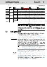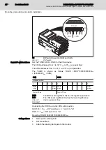
Outputs OUT0 to OUT3
Attainable category
SIL 2/SILCL 2/Cat. 3/PL d SIL 3/SILCL 3/cat. 4/PL e
Pin example
①
If the test pulses are switched off, a cross-fault between the
outputs is only detected if the output is switched on.
Tab. 3-3:
Attainable safety level
To meet category 3, dual-channel actuators are generally used.
3.7
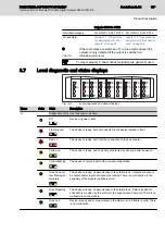
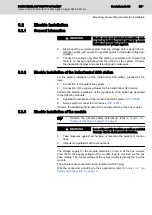
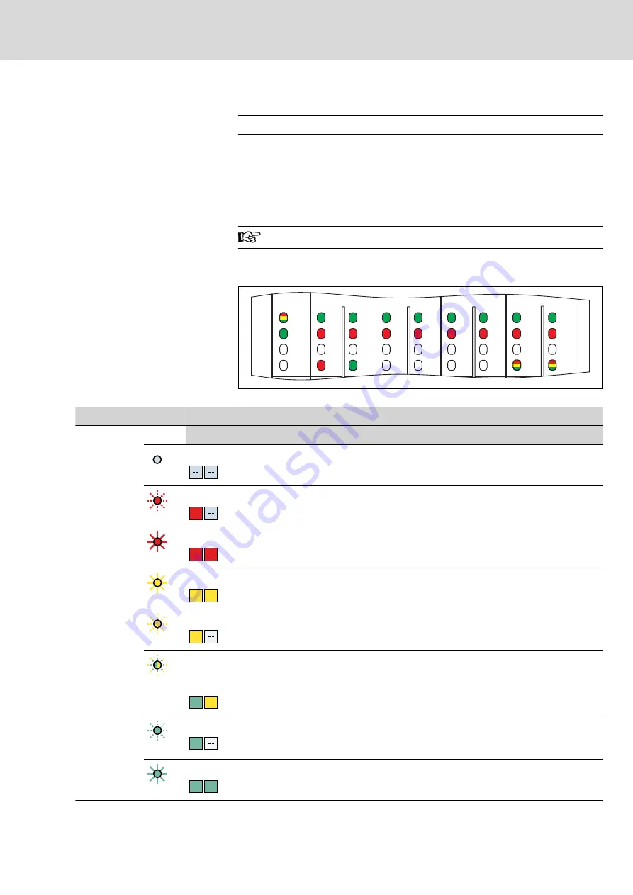
Local diagnostic and status displays
FS P
00
D
Uo
10
01
11
02
12
03
13
04
14
05
15
06
16
07
17
NE
MS
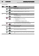
Fig. 3-4:
Local diagnostic and status displays
Name
Color
State
Description
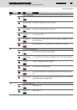
D
Diagnostics of the local bus communication
Off
Device in (power) reset.
Flashing red
RD
The device is ready, but not connected to the device located in front.
Red on
RD RD
The device is ready, but it lost the connection to the bus coupler.
Yellow on
YE YE
The device is ready, but it has not yet detected a valid cycle after power-on.
Yellow flashing
YE
The device is not (yet) part of the current configuration.
Green and yel‐
low flashing al‐
ternately
GN YE
The device is ready. Communication in the station is ok. Output data cannot
be output and/or input data cannot be loaded. There is a malfunction in the
periphery of the module (periphery error).
Green flashing
GN
The device is ready. Communication in the station is ok. Data is invalid. No
valid data is provided by the control or the superimposed network. There is no
malfunction on the module.
Green on
GN GN
Device is ready and communication in the station is ok. All data is valid. There
is no malfunction.
DOK-CONTRL-S20*SSDO*8*-AP02-EN-P
Bosch Rexroth AG
15/85
IndraControl S20 Module With Safe Digital Outputs S20-SSDO-8/3
Product description

