


FPD-7024
|
Operation and Installation Guide | 5.0
Control Panel Programming
56
Bosch Security Systems, Inc. | 1/10 | F01U008458-03
ONBOARD RELAY
(1-3):
Enter the number corresponding to the relay to be programmed and press [#/Enter]. The display asks you to
enter four zones to activate this output:
OUTPUT ZONE A:___
(00 - 63):___
Enter the first zone (00 to 63) you want to assign to this output and press [#/Enter]. A similar display for Zones
B, C and D will appear to allow up to four zones to be assigned to this output. When all four zones are
assigned, the previous window appears.
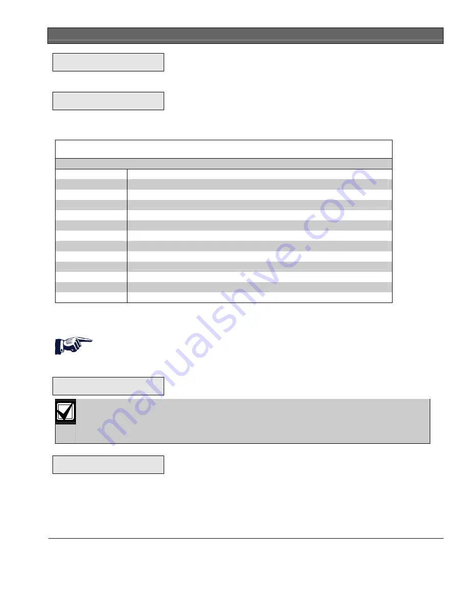
Table 20: Pre-Assigned Zone Quick Reference
Zone Pre-Assigned
Condition
52
General Fire Alarm (non-silencing)
53
General Fire Alarm, (silencing)
54
Ground Start
55
General Supervisory, (silencing)
56
General Waterflow, (silencing)
57 Communication
Trouble
58
General Supervisory Alarm (non-silencing)
59 Alarm
Verification
60
AC Failed
61
General Waterflow Alarm (non-silencing)
62
General Trouble
63
General Alarm, Waterflow Supervisory (non-silencing)
An output point cannot be assigned to more than four zones. Each output does not need to be assigned to
four zones. Each zone can have any number of outputs assigned to it.
Remote Relays
Shortcut: 0-
PROG
,
5-
PROG OUTPUTS
,
2-
RELAYS
The display scrolls through the Relay options. Press [2] for REMOTE 1 or [3] for REMOTE 2. The following
window appears:
REMOTE RELAY @ x
(1 - 8):
The @ x shows the address of the relay module in the system. The lower number address is
Relay 1; the higher one is Relay 2.
When you address a MUX Module, you assign an address. If you have a dual point, it would have
two consecutive addresses.
Enter the relay you wish to assign and press [#/Enter]. The display shows:
OUTPUT ZONE A: __
(00-63):___
Enter the output number (00 to 63) you want to assign to Zone A and press [#/Enter]. A similar display for
Zone B appears. When all four zones are assigned, the previous window appears.