


FPD-7024
|
Operation and Installation Guide | 1.0
Overview
16
Bosch Security Systems, Inc. | 1/10 | F01U008458-03
1.3 Parts
List
•
One FPD-7024 Control/Communicator in
static-resistant bag
•
One enclosure with transformer
•
One hardware pack
•
One enclosure lock, washer, and keys
•
Six end-of-line (EOL) resistors
The hardware necessary for installing the control
panel in the enclosure is located in the hardware
pack.
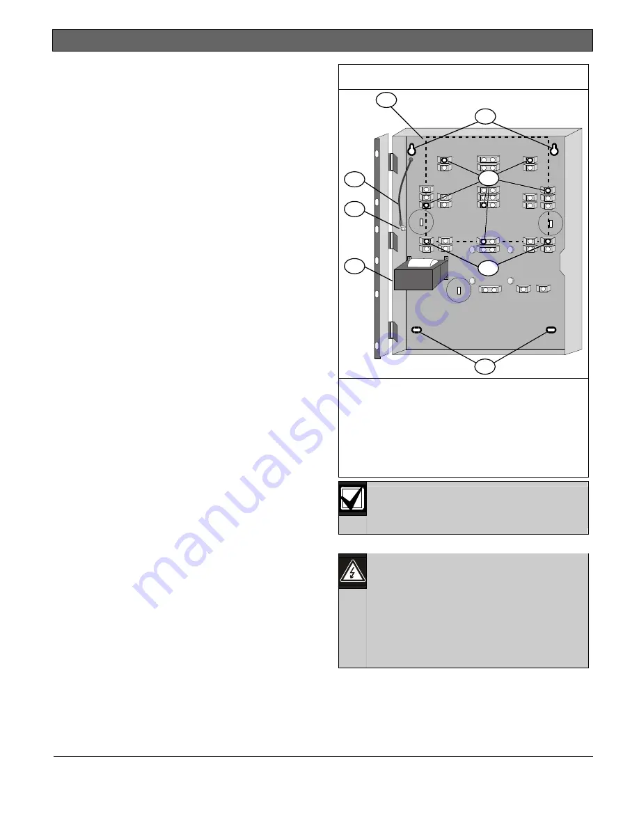
1.4
Installing the Enclosure
1.
Using the enclosure as a template, mark the
top mounting holes on the mounting surface
(
Figure 3).
2.
Start the mounting screws (not supplied) for
these two holes.
3.
Slide the enclosure onto these screws so that
the screws rest on the thinner section of the
holes.
4.
Tighten the screws.
5.
Install and tighten the remaining two screws in
the bottom mounting holes.
6.
Knock out the desired wire entrances on the
enclosure.
Figure 3: Enclosure Installation
2
2
5
7
4
3
1
6
1 - Control panel location
2 - Mounting holes
3 - Retainer holes for standoffs
4 - Retainer holes for support posts
5 - Transformer
6 - Stud
7 - Ground wire
If using the knockouts located at the
bottom of the enclosure install batteries in
a separate enclosure.
1.5
Installing the FPD-7024
The control circuit board in the FPD-7024
is static sensitive. Touch ground before
handling the control board. This
discharges any static electricity in your
body. For example, run the ground wire
to the enclosure before handling the
control circuit board. Continue touching
the enclosure while installing the control
board.
1.
Insert the three support posts in the
enclosure’s retainer holes. Refer to
Figure 3
above and
Figure 4
on page 17.
2.
Press the 1/8 in. nylon standoffs
(P/N: F01U034705) into the retainer holes.