44
DAP - Digital to Analog Processor
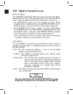
INPUT CH PLAN:
The CHANNEL PLAN mode allows the user to the select the appro-
priate frequency mode. This setting alerts the user to the appropriate
center frequency plan the DAP will use during the scan process.
• The BROADCAST option must be selected for off-air 8VSB
reception, this is automatically set if the DEMOD MODE is set to
8VSB. Reception is limited to VHF & UHF center frequencies.
• The STANDARD CATV mode is capable of locking to QAM Annex
B and 8VSB signals. This channel plan is automatically set when
the QAM B mode is selected in the DEMOD MODE command
menu. Reception is limited to CATV center frequencies.
o It is only required to choose the HRC or IRC option when these
frequency off-sets are used with the CATV plan.
SCAN MENU:
The SCAN MENU command allows the DAP unit to auto search for
available programming. It is required to perform a scan in order to
function properly.
• YES – The YES command performs a scan of the incoming
available signals by the DAP unit
• STATUS – The STATUS command displays the channels found
during the scan process
• STOP SCAN – The STOP SCAN command permits an operator to
stop an in-process scan. It is important to note that
once a scan starts the previously found channel
data is immediately erased. If the scan is stopped,
only the completed scan channel data will be
available for selection
• EXIT – The EXIT command exits the SCAN MENU without making
any modifications
The unit will display the SCAN IN PROCESS message
during the scan process if interaction is attempted.
Содержание AMM-806
Страница 86: ...79 TVCB PC Installation ...
Страница 93: ...86 SMI Installation Torque Patterns 1 Start Here 2 3 4 5 6 1 Start Here 2 3 4 4 PORT 8 PORT ...
Страница 125: ...118 Fiber Optics Fiber Loss vs Path Length Single Mode 1550 nm ...
Страница 156: ...149 Cable TV Channel Format NTSC NTSC Composite Video Waveform ...
Страница 157: ...150 US Frequency Spectrum ...
Страница 158: ...151 FCC Aeronautical Band Frequencies Used for Communication and Navigation ...
Страница 171: ...164 F C x 32 Temperature Conversion Nomograph C F FAHRENHEIT F CELSIUS C 9 5 C F 32 5 9 KELVIN K K C 273 ...
Страница 175: ...168 Common CATV Symbols ...
Страница 176: ...169 Common CATV Symbols ...
Страница 177: ...170 Digital L Band Distribution Symbols ...
Страница 178: ...171 Digital L Band Distribution Symbols ...
Страница 183: ...176 Typical Cable Attenuation Chart in dB 100 Feet 68 F 20 C ...
Страница 187: ...180 Echo Rating Graph ...
Страница 188: ...181 Signal to Interference Limits Non Coherent Carriers ...
Страница 190: ...183 Heterodyne Modulator Analog ...
Страница 191: ...184 Heterodyne Processor Analog ...
Страница 213: ...206 Multiplexers ...
Страница 215: ...208 Antenna Stacking Methods to Increase Received Signal Level NOTE Refer to Antenna Spacing Chart for dimensions ...
Страница 216: ...209 Antenna Spacing Mounting Channelized Antennas on the Same Mast NOTE Refer to Antenna Spacing Chart for dimensions ...
Страница 285: ...Rev 8 0 ...

