
24
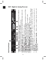
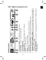
AQM - Agile QAM Modulator
RF OUT
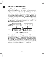
The unit presents a fully modulated QAM RF output. There are
two modes that determine the upconversion programming.
NTSC:
The NTSC mode permits programming the RF output
using a standard NTSC channel number.
MHz:
The MHz or Frequency Tuning mode permits
programming the RF output to the desired frequency.
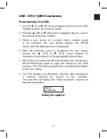
Output
In the NTSC Mode it can be upconverted in 6 MHz increments
to any NTSC standard channel, 2-135 (center frequency). See
Appendix A for Frequency details.
In the MHz or Frequency Mode it can be upconverted to any desired
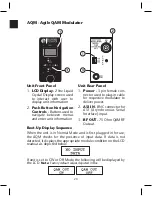
frequency in 12.5 kHz increments. Press the
▲
(UP) or
▼
(DN)
arrow buttons to increment or decrement to the appropriate desired
value for each digit, press and hold the button to quickly scroll.
QAM Out
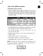
The unit has three QAM modes.
NORMAL: The NORMAL QAM mode outputs a QAM modulated signal.
OFF: The OFF QAM mode outputs no signal from the module.
CW: The CW QAM mode outputs a CW signal that is very useful for
measuring the output level of the unit. (See the QAM Signal Level
Testing section for more detail).
Output Level
The AQM features electronic output level control.
• Can be adjusted in any of the QAM modes listed above.
• Displayed and measured as an average value. (See the QAM
Signal Level Testing section for more detail).
• QAM CW output level is a true representation of a QAM signal level.
The output level range is +30 dBmV to +40 dBmV.
NOTE:
For optimum noise performance, output level for each module
should be set nominally at +40 dBmV.
Содержание AMM-806
Страница 86: ...79 TVCB PC Installation ...
Страница 93: ...86 SMI Installation Torque Patterns 1 Start Here 2 3 4 5 6 1 Start Here 2 3 4 4 PORT 8 PORT ...
Страница 125: ...118 Fiber Optics Fiber Loss vs Path Length Single Mode 1550 nm ...
Страница 156: ...149 Cable TV Channel Format NTSC NTSC Composite Video Waveform ...
Страница 157: ...150 US Frequency Spectrum ...
Страница 158: ...151 FCC Aeronautical Band Frequencies Used for Communication and Navigation ...
Страница 171: ...164 F C x 32 Temperature Conversion Nomograph C F FAHRENHEIT F CELSIUS C 9 5 C F 32 5 9 KELVIN K K C 273 ...
Страница 175: ...168 Common CATV Symbols ...
Страница 176: ...169 Common CATV Symbols ...
Страница 177: ...170 Digital L Band Distribution Symbols ...
Страница 178: ...171 Digital L Band Distribution Symbols ...
Страница 183: ...176 Typical Cable Attenuation Chart in dB 100 Feet 68 F 20 C ...
Страница 187: ...180 Echo Rating Graph ...
Страница 188: ...181 Signal to Interference Limits Non Coherent Carriers ...
Страница 190: ...183 Heterodyne Modulator Analog ...
Страница 191: ...184 Heterodyne Processor Analog ...
Страница 213: ...206 Multiplexers ...
Страница 215: ...208 Antenna Stacking Methods to Increase Received Signal Level NOTE Refer to Antenna Spacing Chart for dimensions ...
Страница 216: ...209 Antenna Spacing Mounting Channelized Antennas on the Same Mast NOTE Refer to Antenna Spacing Chart for dimensions ...
Страница 285: ...Rev 8 0 ...