185
Broadband RF Network Powering
When determining the power supply location in a cable system, it
is important to know OHM’s Law, cable loop resistance, amplifier
current drain and the minimum operating voltage required for
amplifier operation.
The cable resistance is included in the manufacturers specification
sheet. Resistance is usually stated as center conductor, shield,
and loop. Loop resistance is the sum of the center conductor and
shield resistance.
The amplifier current drain and voltage requirements are also part
of the manufacturers specifications.
The ideal location of the power supply is such that the current
supplied flows equally both, away from, and towards the
headend. The total current supplied should be between 80-90%
of the power supply’s rated output. Current passing through
the amplifiers is usually limited to about 6 Amps. Since power
supplies are available with various current handling abilities, one
with slightly higher capability than required should be selected.
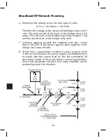
Determining power supply placement, refer to the figure on the
next page.
1. First determine the loop resistance for each span of cable.
Example: Loop resistance = 1.7 Ohms/1000
ft. x 800’ = 1.36 Ohms.
2. Locate the last amplifier, determine the
voltage drop across the span of cable.
3. Using the current draw of the amplifier, determine
the voltage drop across the span of cable.
Example: 0.375A x 1.36 Ohms = 0.51 volts.
4. Since the minimum operating voltage for the amplifier
is 43 volts, the voltage level at the beginning of the
800’ span would be 43.5 volts (43.0 + 0.51).
5. At this point, the total current flow in the coax will increase
due to the addition of another amplifier. Current flow
in this span of cable will be 0.75A (0.375 + 0.375).
Содержание AMM-806
Страница 86: ...79 TVCB PC Installation ...
Страница 93: ...86 SMI Installation Torque Patterns 1 Start Here 2 3 4 5 6 1 Start Here 2 3 4 4 PORT 8 PORT ...
Страница 125: ...118 Fiber Optics Fiber Loss vs Path Length Single Mode 1550 nm ...
Страница 156: ...149 Cable TV Channel Format NTSC NTSC Composite Video Waveform ...
Страница 157: ...150 US Frequency Spectrum ...
Страница 158: ...151 FCC Aeronautical Band Frequencies Used for Communication and Navigation ...
Страница 171: ...164 F C x 32 Temperature Conversion Nomograph C F FAHRENHEIT F CELSIUS C 9 5 C F 32 5 9 KELVIN K K C 273 ...
Страница 175: ...168 Common CATV Symbols ...
Страница 176: ...169 Common CATV Symbols ...
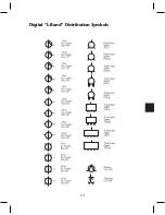
Страница 177: ...170 Digital L Band Distribution Symbols ...
Страница 178: ...171 Digital L Band Distribution Symbols ...
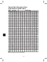
Страница 183: ...176 Typical Cable Attenuation Chart in dB 100 Feet 68 F 20 C ...
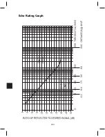
Страница 187: ...180 Echo Rating Graph ...
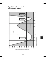
Страница 188: ...181 Signal to Interference Limits Non Coherent Carriers ...
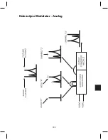
Страница 190: ...183 Heterodyne Modulator Analog ...
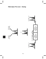
Страница 191: ...184 Heterodyne Processor Analog ...
Страница 213: ...206 Multiplexers ...
Страница 215: ...208 Antenna Stacking Methods to Increase Received Signal Level NOTE Refer to Antenna Spacing Chart for dimensions ...
Страница 216: ...209 Antenna Spacing Mounting Channelized Antennas on the Same Mast NOTE Refer to Antenna Spacing Chart for dimensions ...
Страница 285: ...Rev 8 0 ...

