122
Fiber Optics
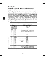
FRDA/FRRA Series RF Attenuation Requirements
The RF output level from the optical receiver module varies consider-
ably over its operational optical input range. It is also dependent upon
the transmitter’s channel loading, its resultant RF input level and the
FRRA/FRDA RF output capability. In order not to overload the ampli-
fier section input, an internal attenuator must be installed. To find the
recommended attenuator value, first determine the receivers opti-
cal input level as noted in the "Input Optical Power”. Refer to the
Configuration Table below, locate the power monitor voltage or
input dBm in the left hand columns. Read across on the corre-
sponding row to find the value required.
G
R
E
E
N
L
E
D
Model
FRRA-S4A-860P
CH. Loading
110 CH.
Output Level
34/42
Optical Input
dBm mW
-10
0.10
-9
0.13
-8
0.16
-7
0.20
-6
0.25
0 dB
-5
0.32
2 dB
-4
0.40
4 dB
-3
0.50
6 dB
-2
0.63
8 dB
-1
0.79
10 dB
0
1.00
12 dB
1
1.26
14 dB
2
1.58
16 dB
3
2.00
18 dB
4
2.51
5
3.16
Increase Optical Input Power
Orange Optical LED Indication
Decrease Optical Input Power
Red Optical LED Indication
Recommended
Attenuator
Value
Содержание AMM-806
Страница 86: ...79 TVCB PC Installation ...
Страница 93: ...86 SMI Installation Torque Patterns 1 Start Here 2 3 4 5 6 1 Start Here 2 3 4 4 PORT 8 PORT ...
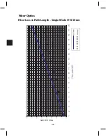
Страница 125: ...118 Fiber Optics Fiber Loss vs Path Length Single Mode 1550 nm ...
Страница 156: ...149 Cable TV Channel Format NTSC NTSC Composite Video Waveform ...
Страница 157: ...150 US Frequency Spectrum ...
Страница 158: ...151 FCC Aeronautical Band Frequencies Used for Communication and Navigation ...
Страница 171: ...164 F C x 32 Temperature Conversion Nomograph C F FAHRENHEIT F CELSIUS C 9 5 C F 32 5 9 KELVIN K K C 273 ...
Страница 175: ...168 Common CATV Symbols ...
Страница 176: ...169 Common CATV Symbols ...
Страница 177: ...170 Digital L Band Distribution Symbols ...
Страница 178: ...171 Digital L Band Distribution Symbols ...
Страница 183: ...176 Typical Cable Attenuation Chart in dB 100 Feet 68 F 20 C ...
Страница 187: ...180 Echo Rating Graph ...
Страница 188: ...181 Signal to Interference Limits Non Coherent Carriers ...
Страница 190: ...183 Heterodyne Modulator Analog ...
Страница 191: ...184 Heterodyne Processor Analog ...
Страница 213: ...206 Multiplexers ...
Страница 215: ...208 Antenna Stacking Methods to Increase Received Signal Level NOTE Refer to Antenna Spacing Chart for dimensions ...
Страница 216: ...209 Antenna Spacing Mounting Channelized Antennas on the Same Mast NOTE Refer to Antenna Spacing Chart for dimensions ...
Страница 285: ...Rev 8 0 ...

