36
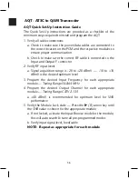
AQT Quick Set-Up Instruction Guide
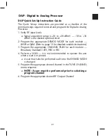
The Quick Set-Up instructions are provided as a checklist of the
minimum steps required to install and program the AQT.
1. Verify all cable connections
a. Check to make sure the power/data cables are connected to
the correct location on the PCM and the respective modules to
ensure proper communication
b. Check to make sure the correct RF cable is connected to the
Input and Output F connector
2. Verify RF input levels
a. Signal acquisition range is -20 to +20 dBmV — -10 to +10
dBmV is the desired optimum level
3. Program the desired Input Frequency for each appropriate
module —
Tuning Range 54-864 MHz
4. Program the desired Output Channel for each appropriate
module —
Tuning Range CATV 2-135
a. +40 dBmV is recommended for optimum level for SNR
performance
5. Verify the Module Lock state —
Press the
u
(R) arrow key until
the SNR value is shown for the appropriate module
a. If not locked, activate the Input Browse mode for the module,
this will auto search & tune all pre-programmed modes
b. Verify input signal level, feed/cable
NOTE:
Repeat as appropriate for each module
AQT - ATSC to QAM Transcoder
Содержание AMM-806
Страница 86: ...79 TVCB PC Installation ...
Страница 93: ...86 SMI Installation Torque Patterns 1 Start Here 2 3 4 5 6 1 Start Here 2 3 4 4 PORT 8 PORT ...
Страница 125: ...118 Fiber Optics Fiber Loss vs Path Length Single Mode 1550 nm ...
Страница 156: ...149 Cable TV Channel Format NTSC NTSC Composite Video Waveform ...
Страница 157: ...150 US Frequency Spectrum ...
Страница 158: ...151 FCC Aeronautical Band Frequencies Used for Communication and Navigation ...
Страница 171: ...164 F C x 32 Temperature Conversion Nomograph C F FAHRENHEIT F CELSIUS C 9 5 C F 32 5 9 KELVIN K K C 273 ...
Страница 175: ...168 Common CATV Symbols ...
Страница 176: ...169 Common CATV Symbols ...
Страница 177: ...170 Digital L Band Distribution Symbols ...
Страница 178: ...171 Digital L Band Distribution Symbols ...
Страница 183: ...176 Typical Cable Attenuation Chart in dB 100 Feet 68 F 20 C ...
Страница 187: ...180 Echo Rating Graph ...
Страница 188: ...181 Signal to Interference Limits Non Coherent Carriers ...
Страница 190: ...183 Heterodyne Modulator Analog ...
Страница 191: ...184 Heterodyne Processor Analog ...
Страница 213: ...206 Multiplexers ...
Страница 215: ...208 Antenna Stacking Methods to Increase Received Signal Level NOTE Refer to Antenna Spacing Chart for dimensions ...
Страница 216: ...209 Antenna Spacing Mounting Channelized Antennas on the Same Mast NOTE Refer to Antenna Spacing Chart for dimensions ...
Страница 285: ...Rev 8 0 ...

