
112
-65
-60
-58
20
20
20
-3.25 - 3.00 - 2.90
-4
-3
-3
-4
-4
-4
-4
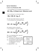
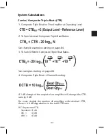
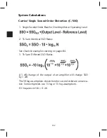
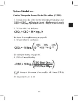
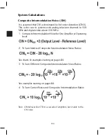
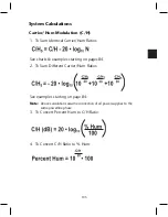
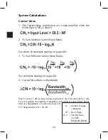
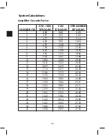
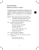
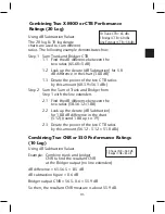
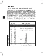
System Calculations
Note:
Summing different ratios requires a grasp of the antilog concept.
For brevity, the example shown is for CTB only, but the approach is
identical for all system distortion and noise calculations.
Determine End Of Line CTB Given The Following:
10 Trunk CTB = 65 dBc
1 Bridger CTB = 60 dBc
3 Line Extender CTB = 58 dBc
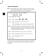
Step 1. CTBs = 20 log (10 + 10 + 10 )
Step 2. CTBs = 20 log (10 +10 +10 )
CTBs 20 log (antilog -3.25 + antilog -3.00 + antilog -2.90)
Note:
To perform the operations in step 2, use the “inverse” log or “antilog”
function on most calculators. Antilog (Inverse Log) is used to re-express
the different exponent values to voltage so the amounts may be easily
summed. Don’t forget the minus sign.
Step 3. CTBs = 20 log (5.62 x 10 + 1 x 10 + 1.26 x 10 )
Step 4. CTBs = 20 log (5.62 x 10 + 10 x 10 + 12.6 x 10 )
Step 5. CTBs = 20 log (28.12 x 10 )
CTB = 51 dBc
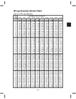
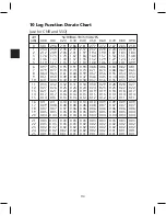
The 20 Log and 10 Log function derate charts & example on pages 86, 87
and 88 may also be used to sum different ratios if a scientific calculator is
not available.
Содержание AMM-806
Страница 86: ...79 TVCB PC Installation ...
Страница 93: ...86 SMI Installation Torque Patterns 1 Start Here 2 3 4 5 6 1 Start Here 2 3 4 4 PORT 8 PORT ...
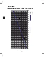
Страница 125: ...118 Fiber Optics Fiber Loss vs Path Length Single Mode 1550 nm ...
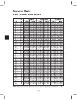
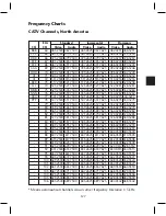
Страница 156: ...149 Cable TV Channel Format NTSC NTSC Composite Video Waveform ...
Страница 157: ...150 US Frequency Spectrum ...
Страница 158: ...151 FCC Aeronautical Band Frequencies Used for Communication and Navigation ...
Страница 171: ...164 F C x 32 Temperature Conversion Nomograph C F FAHRENHEIT F CELSIUS C 9 5 C F 32 5 9 KELVIN K K C 273 ...
Страница 175: ...168 Common CATV Symbols ...
Страница 176: ...169 Common CATV Symbols ...
Страница 177: ...170 Digital L Band Distribution Symbols ...
Страница 178: ...171 Digital L Band Distribution Symbols ...
Страница 183: ...176 Typical Cable Attenuation Chart in dB 100 Feet 68 F 20 C ...
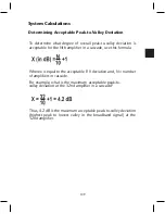
Страница 187: ...180 Echo Rating Graph ...
Страница 188: ...181 Signal to Interference Limits Non Coherent Carriers ...
Страница 190: ...183 Heterodyne Modulator Analog ...
Страница 191: ...184 Heterodyne Processor Analog ...
Страница 213: ...206 Multiplexers ...
Страница 215: ...208 Antenna Stacking Methods to Increase Received Signal Level NOTE Refer to Antenna Spacing Chart for dimensions ...
Страница 216: ...209 Antenna Spacing Mounting Channelized Antennas on the Same Mast NOTE Refer to Antenna Spacing Chart for dimensions ...
Страница 285: ...Rev 8 0 ...