
15
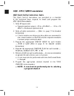
AQD - ATSC/QAM Demodulator
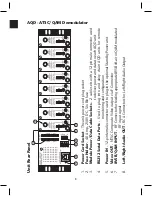
TUNE CHANNEL:
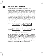
The Tune Channel command allows a user to select
the desired program from the list of available channels from the unit
scan. To select a program scroll to the desired item in the channel list
and press the Enter key.
• Depress the
p
(UP) arrow navigation key to scroll through all the
available channels (major and minor sub-channel)
• Depressing the
q
(DN) arrow navigation key permits faster tuning by
'jumping' to each major channel available from the scan.
o Tuning to the desired minor sub-channel is then easy by pressing the
p
(UP) arrow navigation key
The LCD will show the ENTRY ACCEPTED message and all TV’s will
briefly display a banner at the top of the screen. The banner contains the
major & minor sub-channel designation and the time (time displayed
comes from the broadcast stream).
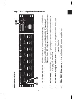
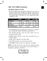
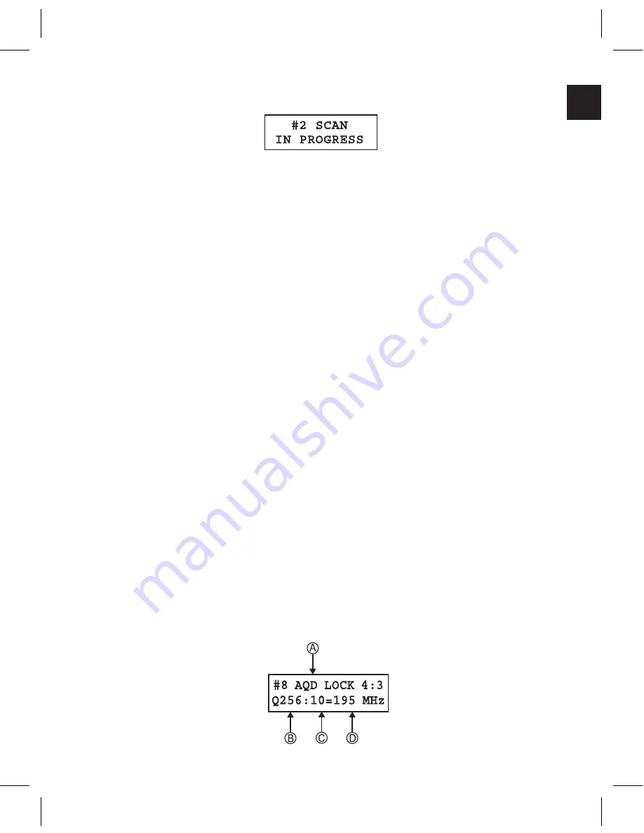
AQD STATUS -
The AQD Status command screen displays
valuable status information on the selected program channel.
Signal Status:
A
.
LOCK
is indicated when a valid signal acquisition has been
achieved by the AQD module as well as the signal aspect ratio.
NOT LOCKED
will be displayed if the module fails to acquire the
desired program signal Channel Frequency Data:
B.
INPUT SIGNAL TYPE IS DISPLAYED –
Such as UHF or 64 or
256 QAM
C.
THE INPUT SIGNAL CH. IS DISPLAYED –
for example, CH 44
D
.
THE CORRESPONDING FREQUENCY FOR THE INPUT CH.
–
653 MHz for CH 44 UHF
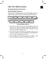
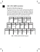
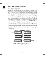
The unit will display the SCAN IN PROCESS message during the scan
process if interaction is attempted within the active scanning AQD module.
Содержание AMM-806
Страница 86: ...79 TVCB PC Installation ...
Страница 93: ...86 SMI Installation Torque Patterns 1 Start Here 2 3 4 5 6 1 Start Here 2 3 4 4 PORT 8 PORT ...
Страница 125: ...118 Fiber Optics Fiber Loss vs Path Length Single Mode 1550 nm ...
Страница 156: ...149 Cable TV Channel Format NTSC NTSC Composite Video Waveform ...
Страница 157: ...150 US Frequency Spectrum ...
Страница 158: ...151 FCC Aeronautical Band Frequencies Used for Communication and Navigation ...
Страница 171: ...164 F C x 32 Temperature Conversion Nomograph C F FAHRENHEIT F CELSIUS C 9 5 C F 32 5 9 KELVIN K K C 273 ...
Страница 175: ...168 Common CATV Symbols ...
Страница 176: ...169 Common CATV Symbols ...
Страница 177: ...170 Digital L Band Distribution Symbols ...
Страница 178: ...171 Digital L Band Distribution Symbols ...
Страница 183: ...176 Typical Cable Attenuation Chart in dB 100 Feet 68 F 20 C ...
Страница 187: ...180 Echo Rating Graph ...
Страница 188: ...181 Signal to Interference Limits Non Coherent Carriers ...
Страница 190: ...183 Heterodyne Modulator Analog ...
Страница 191: ...184 Heterodyne Processor Analog ...
Страница 213: ...206 Multiplexers ...
Страница 215: ...208 Antenna Stacking Methods to Increase Received Signal Level NOTE Refer to Antenna Spacing Chart for dimensions ...
Страница 216: ...209 Antenna Spacing Mounting Channelized Antennas on the Same Mast NOTE Refer to Antenna Spacing Chart for dimensions ...
Страница 285: ...Rev 8 0 ...