

111
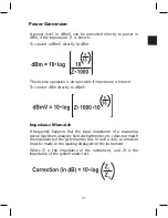
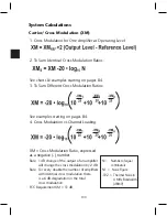
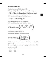
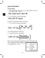
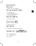
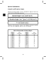
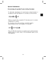
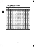
System Calculations
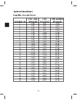
The Amplifier Cascade Factor Chart (on previous page) is used
to predict performance considering the contribution of various
numbers of amplifiers. It assumes that all amplifiers are
operated at the same level (input level for noise, output level
for distortion). This is generally the case in a Unity Gain Based
System.
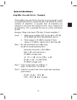
Example: What is the trunk CTB after 13 trunk amplifiers?
Given: 1. Single trunk amplifier CTB specification is 87 dB
@ 32 dBmV flat (from Manufacturers specs.)
2. Trunk output is 25 dBmV, channel 2 Trunk
output is 32 dBmV, channel 60 (7 dB linear tilt)
Step 1 Re-rate performance of single amp
based on actual operating level.
Geometric tilt center = 28.5 dBmV
Add .5 dB correction factor =
29 dBmV average level
32 - 29 = 3 dB x 2 (for CTB) = 6 dB
87 dB + 6 dB = 93 dB CTB @
29 dBmV average level
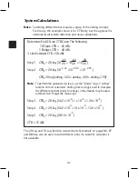
Step 2 Find cascade factor for CTB for 13
amps, on the chart = 22.28 dB
Step 3 Subtract cascade factor from single amp operating
performance
93 dB - 22.28 = 70.72 dB
CTB = 70.72 dB after 13 amps
Amplifier Cascade Factor - Example
Содержание AMM-806
Страница 86: ...79 TVCB PC Installation ...
Страница 93: ...86 SMI Installation Torque Patterns 1 Start Here 2 3 4 5 6 1 Start Here 2 3 4 4 PORT 8 PORT ...
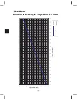
Страница 125: ...118 Fiber Optics Fiber Loss vs Path Length Single Mode 1550 nm ...
Страница 156: ...149 Cable TV Channel Format NTSC NTSC Composite Video Waveform ...
Страница 157: ...150 US Frequency Spectrum ...
Страница 158: ...151 FCC Aeronautical Band Frequencies Used for Communication and Navigation ...
Страница 171: ...164 F C x 32 Temperature Conversion Nomograph C F FAHRENHEIT F CELSIUS C 9 5 C F 32 5 9 KELVIN K K C 273 ...
Страница 175: ...168 Common CATV Symbols ...
Страница 176: ...169 Common CATV Symbols ...
Страница 177: ...170 Digital L Band Distribution Symbols ...
Страница 178: ...171 Digital L Band Distribution Symbols ...
Страница 183: ...176 Typical Cable Attenuation Chart in dB 100 Feet 68 F 20 C ...
Страница 187: ...180 Echo Rating Graph ...
Страница 188: ...181 Signal to Interference Limits Non Coherent Carriers ...
Страница 190: ...183 Heterodyne Modulator Analog ...
Страница 191: ...184 Heterodyne Processor Analog ...
Страница 213: ...206 Multiplexers ...
Страница 215: ...208 Antenna Stacking Methods to Increase Received Signal Level NOTE Refer to Antenna Spacing Chart for dimensions ...
Страница 216: ...209 Antenna Spacing Mounting Channelized Antennas on the Same Mast NOTE Refer to Antenna Spacing Chart for dimensions ...
Страница 285: ...Rev 8 0 ...