175
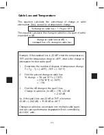
This equation calculates the percentage of change in cable
attenuation (loss) caused by a temperature change:
% change in cable loss = 1.1% per 10° F
This equation calculates the change in cable loss in a span of cable,
expressed in dB.
change in cable loss (in dB) =
standard loss x % change in cable loss
Cable Loss and Temperature
Example: If the standard loss is 22 dB* when the temperature is
70°F and the temperature drops to -40°F, what is the change in
attenuation for that cable span?
1. Determine the number of degrees of temperature change.
T = T2 - T1 = (-40°F) - 70°F = (-110° F)
2. Find the percent change in cable loss.
% change = 1% per 10°F x (-110°F)
= (1%/10°F) x (-110°F)
= - 11%
3. Find the dB change in the span’s loss.
Change in cable loss (in dB) = -11% x 22 dB
= -2.42 dB
So, if the span’s loss was 22 dB at 70°F it becomes
22 dB + (-2.42 dB) = 19.58 dB at -40°F.
Changes in cable loss accumulate over multiple cable spans
and can cause performance degradation if not controlled by
AGC/ASC units.
Содержание AMM-806
Страница 86: ...79 TVCB PC Installation ...
Страница 93: ...86 SMI Installation Torque Patterns 1 Start Here 2 3 4 5 6 1 Start Here 2 3 4 4 PORT 8 PORT ...
Страница 125: ...118 Fiber Optics Fiber Loss vs Path Length Single Mode 1550 nm ...
Страница 156: ...149 Cable TV Channel Format NTSC NTSC Composite Video Waveform ...
Страница 157: ...150 US Frequency Spectrum ...
Страница 158: ...151 FCC Aeronautical Band Frequencies Used for Communication and Navigation ...
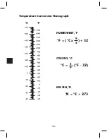
Страница 171: ...164 F C x 32 Temperature Conversion Nomograph C F FAHRENHEIT F CELSIUS C 9 5 C F 32 5 9 KELVIN K K C 273 ...
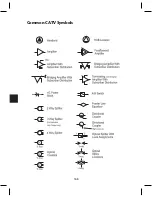
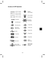
Страница 175: ...168 Common CATV Symbols ...
Страница 176: ...169 Common CATV Symbols ...
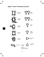
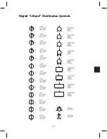
Страница 177: ...170 Digital L Band Distribution Symbols ...
Страница 178: ...171 Digital L Band Distribution Symbols ...
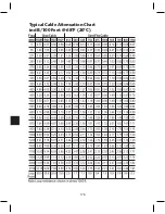
Страница 183: ...176 Typical Cable Attenuation Chart in dB 100 Feet 68 F 20 C ...
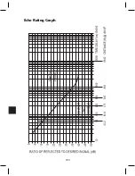
Страница 187: ...180 Echo Rating Graph ...
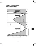
Страница 188: ...181 Signal to Interference Limits Non Coherent Carriers ...
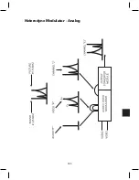
Страница 190: ...183 Heterodyne Modulator Analog ...
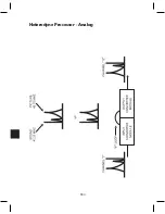
Страница 191: ...184 Heterodyne Processor Analog ...
Страница 213: ...206 Multiplexers ...
Страница 215: ...208 Antenna Stacking Methods to Increase Received Signal Level NOTE Refer to Antenna Spacing Chart for dimensions ...
Страница 216: ...209 Antenna Spacing Mounting Channelized Antennas on the Same Mast NOTE Refer to Antenna Spacing Chart for dimensions ...
Страница 285: ...Rev 8 0 ...

