179
Ghosts
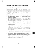
Ghosts are duplicates of the reproduced picture located to the right
or left of the picture. Ghosts displaced to the left are generally due
to ingress, for example, direct pick up. Assuming ghosts are not
present in the signals at the headend, ghosts displaced to the right
are generally indicative of impedance mismatches in the system,
for example, devices with poor return loss.
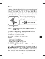
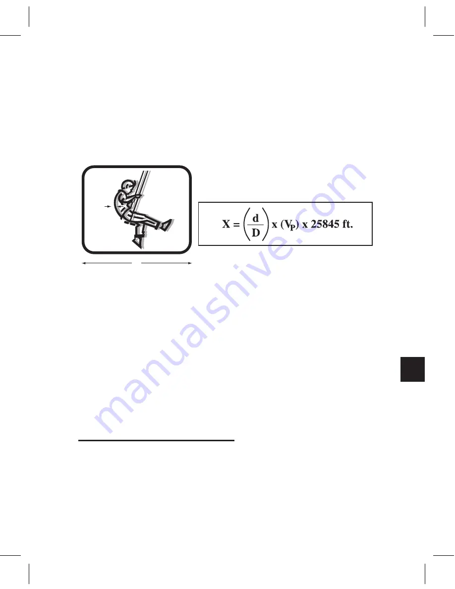
The following will help to find the
cause of a ghost that is displaced
to the right.
d
D
25845 = constant derived from speed of light x scan time for
horizontal line
X = distance in feet between the source of reflection and re-reflection
d = displacement of ghost on TV set in inches
D = horizontal width of TV set in inches
Vp = Velocity of Propagation referenced to free air
Example:
TV screen, D = 24 inches wide
Ghost image, d = 0.16 inches wide
Velocity of propagation for cable, Vp = 0.88
X = (25845 ft) x (0.16 in) x (0.88)
= 152 ft between devices
24 in
.
Once distance X is calculated, check the system maps for both (1)
the circumstance
where there are devices that are approximately
distance X apart and (2) that
the circumstance
is between to the
signal source and the location where the ghost is being viewed.
Содержание AMM-806
Страница 86: ...79 TVCB PC Installation ...
Страница 93: ...86 SMI Installation Torque Patterns 1 Start Here 2 3 4 5 6 1 Start Here 2 3 4 4 PORT 8 PORT ...
Страница 125: ...118 Fiber Optics Fiber Loss vs Path Length Single Mode 1550 nm ...
Страница 156: ...149 Cable TV Channel Format NTSC NTSC Composite Video Waveform ...
Страница 157: ...150 US Frequency Spectrum ...
Страница 158: ...151 FCC Aeronautical Band Frequencies Used for Communication and Navigation ...
Страница 171: ...164 F C x 32 Temperature Conversion Nomograph C F FAHRENHEIT F CELSIUS C 9 5 C F 32 5 9 KELVIN K K C 273 ...
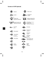
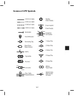
Страница 175: ...168 Common CATV Symbols ...
Страница 176: ...169 Common CATV Symbols ...
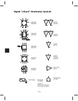
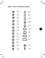
Страница 177: ...170 Digital L Band Distribution Symbols ...
Страница 178: ...171 Digital L Band Distribution Symbols ...
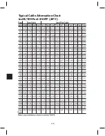
Страница 183: ...176 Typical Cable Attenuation Chart in dB 100 Feet 68 F 20 C ...
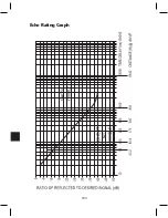
Страница 187: ...180 Echo Rating Graph ...
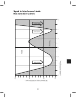
Страница 188: ...181 Signal to Interference Limits Non Coherent Carriers ...
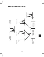
Страница 190: ...183 Heterodyne Modulator Analog ...
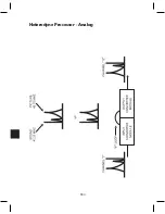
Страница 191: ...184 Heterodyne Processor Analog ...
Страница 213: ...206 Multiplexers ...
Страница 215: ...208 Antenna Stacking Methods to Increase Received Signal Level NOTE Refer to Antenna Spacing Chart for dimensions ...
Страница 216: ...209 Antenna Spacing Mounting Channelized Antennas on the Same Mast NOTE Refer to Antenna Spacing Chart for dimensions ...
Страница 285: ...Rev 8 0 ...

