38
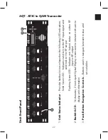
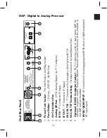
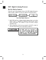
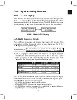
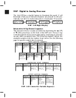
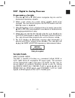
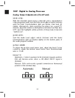
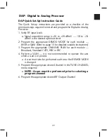
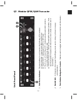
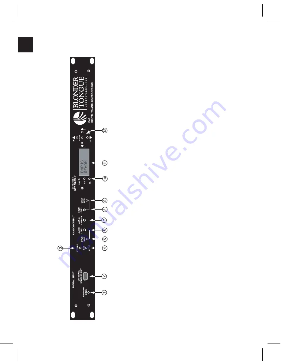
DAP - Digital to Analog Processor
U
ni
t
Fr
on
t
Pa
ne
l
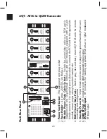
1.
Unit
Status
Indicator
-
Provides
feedback
to
user
based
on
the
following
LED
conditions:
Solid
Green
LED
indicates
valid
lock
to
the
RF
input
signal
Flashing
Green
LED
indicates
N
OT
L
OCKED
or
SCANNING
in
process
2.
9-Pin
RS-2
32
Connector
-
Used
for
future
software
upgrade
of
digital
input
section
only
3.
Stereo
LED
-
Green
stereo
LED
light
4.
EAS/ALT
Indicator
-
R
ed
LED
when
EAS/AL
T
IF
is
active
5.
Audio
Over
Modulation
LED
-
Lights
when
peak
deviation
of
aural
carrier
is
over
25
kHz
6.
Audio
Modulation
Level
-
A
djusts
aural
carrier
modulation
7.
Aural
Carrier
-
C
ontrols
amplitude
of
aural
RF
carrier
relative
to
visual
RF
carrier
8.
Video
Modulation
Level
-
A
djust
per
centage
of
modulation
9.
Video
Over
Modulation
LED
-
Lights
when
modulation
is
above
87.5%
10.
Ethernet
Link,
Receive
and
Transmit
LED
-
L
ED
i
nd
ic
at
or
f
or
o
pt
io
na
l
et
he
rn
et
co
nn
ec
tiv
ity
.
Th
e
LE
D
's
w
ill
o
nl
y
lig
ht
i
f
RN
C
o
pt
io
n
is
in
st
al
le
d
an
d
in
u
se
,
w
ith
ou
t
RN
C
installed
all
LED's
will
be
off.
11.
Backlit
LCD
-
1
6
ch
ar
ac
te
r,
2
lin
e
Li
qu
id
C
ry
st
al
D
isp
la
y
sc
re
en
u
se
d
to
in
te
ra
ct
w
ith
u
se
r
to
display
unit
info
12.
Push
Button
Navigation
Controls
-
B
ut
to
ns
u
se
d
to
n
av
ig
at
e
be
tw
ee
n
m
en
us
a
nd
operate
the
unit
Содержание AMM-806
Страница 86: ...79 TVCB PC Installation ...
Страница 93: ...86 SMI Installation Torque Patterns 1 Start Here 2 3 4 5 6 1 Start Here 2 3 4 4 PORT 8 PORT ...
Страница 125: ...118 Fiber Optics Fiber Loss vs Path Length Single Mode 1550 nm ...
Страница 156: ...149 Cable TV Channel Format NTSC NTSC Composite Video Waveform ...
Страница 157: ...150 US Frequency Spectrum ...
Страница 158: ...151 FCC Aeronautical Band Frequencies Used for Communication and Navigation ...
Страница 171: ...164 F C x 32 Temperature Conversion Nomograph C F FAHRENHEIT F CELSIUS C 9 5 C F 32 5 9 KELVIN K K C 273 ...
Страница 175: ...168 Common CATV Symbols ...
Страница 176: ...169 Common CATV Symbols ...
Страница 177: ...170 Digital L Band Distribution Symbols ...
Страница 178: ...171 Digital L Band Distribution Symbols ...
Страница 183: ...176 Typical Cable Attenuation Chart in dB 100 Feet 68 F 20 C ...
Страница 187: ...180 Echo Rating Graph ...
Страница 188: ...181 Signal to Interference Limits Non Coherent Carriers ...
Страница 190: ...183 Heterodyne Modulator Analog ...
Страница 191: ...184 Heterodyne Processor Analog ...
Страница 213: ...206 Multiplexers ...
Страница 215: ...208 Antenna Stacking Methods to Increase Received Signal Level NOTE Refer to Antenna Spacing Chart for dimensions ...
Страница 216: ...209 Antenna Spacing Mounting Channelized Antennas on the Same Mast NOTE Refer to Antenna Spacing Chart for dimensions ...
Страница 285: ...Rev 8 0 ...