44
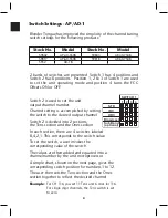
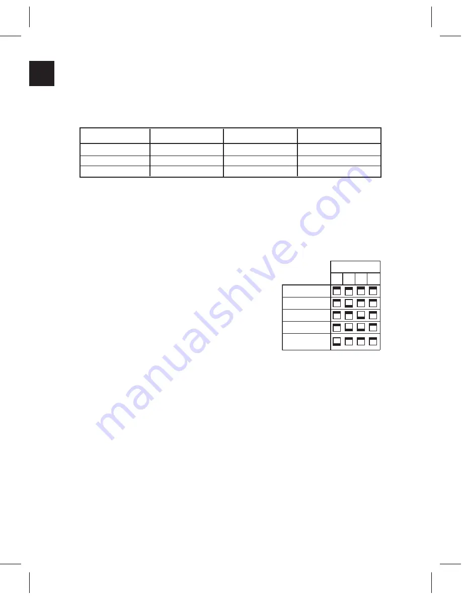
Switch Settings - AP/AD-1
Blonder Tongue has improved the simplicity of the channel tuning
switch settings for the following products:
1
2
3
4
SWITCH 1
STD
IRC
HRC
Broadcast
Sub Band
(optional)
Switch 2 is used to set the unit
output channel number.
Channel setting is accomplished by setting
the switch to the desired output channel.
Switch 2 is divided into 2 sections,
the Tens section and the Ones section.
In each section, there are 4 switches labeled
8,4,2,1. This corresponds to the switch value.
To set the switch, a user invokes the
corresponding value of the switch.
The values are then added and equated into a
channel number by the unit microprocessor.
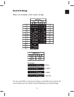
A simple chart, shown on the next page, gives the
corresponding switch position for numbers 1 to 12.
The user then sets the Tens section and the Ones
section together to reflect the desired channel.
Example:
For CH 116, you set 11 Tens and 6 ones for 116.
For single digit channels, the Tens switch is set
to zero.
2 banks of switches are presented. Switch 1 has 4 positions and
Switch 2 has 8 positions. Position 1, 2 & 3 of Switch 1 are used
to set the unit operating mode and position 4 turns the FCC
Offsets ON or OFF.
Stock No.
Model
Stock No.
Model
59802
AP-40-550B
59803
AP-40-750B
59817
AP-60-550B
59818
AP-60-750B
5932
AD-1B
Содержание AMM-806
Страница 86: ...79 TVCB PC Installation ...
Страница 93: ...86 SMI Installation Torque Patterns 1 Start Here 2 3 4 5 6 1 Start Here 2 3 4 4 PORT 8 PORT ...
Страница 125: ...118 Fiber Optics Fiber Loss vs Path Length Single Mode 1550 nm ...
Страница 156: ...149 Cable TV Channel Format NTSC NTSC Composite Video Waveform ...
Страница 157: ...150 US Frequency Spectrum ...
Страница 158: ...151 FCC Aeronautical Band Frequencies Used for Communication and Navigation ...
Страница 171: ...164 F C x 32 Temperature Conversion Nomograph C F FAHRENHEIT F CELSIUS C 9 5 C F 32 5 9 KELVIN K K C 273 ...
Страница 175: ...168 Common CATV Symbols ...
Страница 176: ...169 Common CATV Symbols ...
Страница 177: ...170 Digital L Band Distribution Symbols ...
Страница 178: ...171 Digital L Band Distribution Symbols ...
Страница 183: ...176 Typical Cable Attenuation Chart in dB 100 Feet 68 F 20 C ...
Страница 187: ...180 Echo Rating Graph ...
Страница 188: ...181 Signal to Interference Limits Non Coherent Carriers ...
Страница 190: ...183 Heterodyne Modulator Analog ...
Страница 191: ...184 Heterodyne Processor Analog ...
Страница 213: ...206 Multiplexers ...
Страница 215: ...208 Antenna Stacking Methods to Increase Received Signal Level NOTE Refer to Antenna Spacing Chart for dimensions ...
Страница 216: ...209 Antenna Spacing Mounting Channelized Antennas on the Same Mast NOTE Refer to Antenna Spacing Chart for dimensions ...
Страница 285: ...Rev 8 0 ...


