


VisiPC Software Manual Part 1 – Visilynx 3 Configurator
INS00231 Issue 4 Page 83 of 88
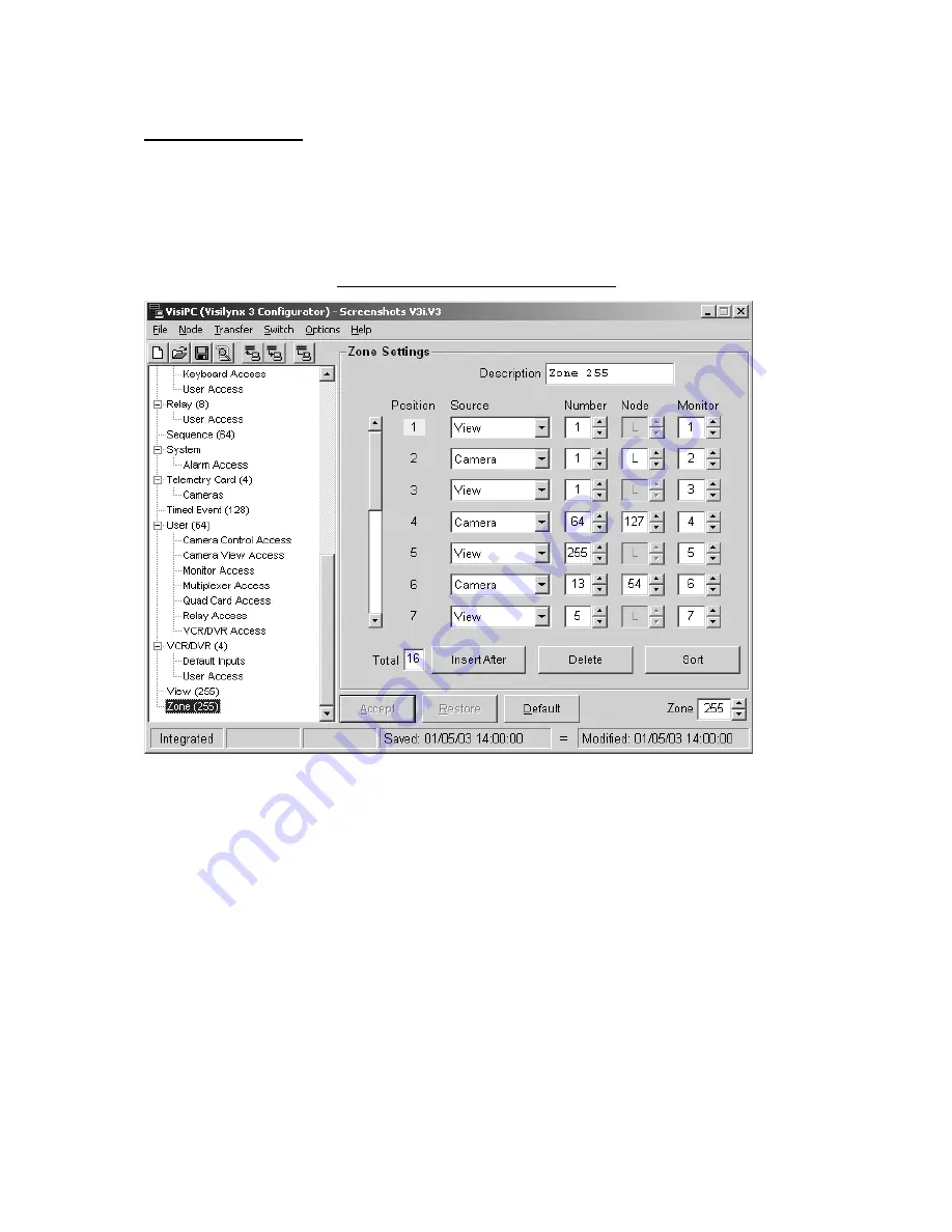
4.21 Zone Settings
‘Zone Settings’ allows a zone, containing up to 31 camera-monitor pairs, to be defined. A
‘Zone’ is a view of a scene from various cameras spread across a set of monitors
simultaneously. This type of zone is different from that programmed at a keyboard.
Keyboard zones do not contain monitor numbers; they use instead the keyboard’s own ‘Zone
Monitors’ as defined in ‘Keyboard Settings’ (see page 33).
Figure 76 Zone Settings Screenshot
•
Use the
Zone
selector (bottom right) to select the one to configure.
•
Description
: Each zone can be given a name, up to 16 characters long, e.g.
STATION-
PLATFORM
.
•
Position
: Each zone position is allocated a number. The currently selected position is
always highlighted. Up to 7 positions can be viewed on screen at once. As soon as an
eighth position is inserted, a scroll bar appears on the left-hand side of the screen to
enable you to view up to 31 positions.
•
Source
: The video source for each position is derived from either a camera or a view.
Note that if a view is selected, the node box will become inactive because the node will
already have been defined in ‘View Settings’ (see page 82). In the example shown
above, Position 1 has View number 1 routed to Monitor 1.
•
Number
: Select the Camera or View number.
•
Node
: If the video source for the position is a camera, the node must now be identified.
In the example shown above, the selected node for position 2 is the local node, ‘L’.