Manual 2100-642
Page
44 of 82
CONTROLLER INTERFACE MENU
STRUCTURE
On/Off Unit
Setpoints
Clock/Scheduler
Input/Output
Analog Inputs
Digital Inputs
Relay Outputs
Analog Outputs
Alarm History
Board Switch
Technician
Information
BMS Configuration
Service Settings
I/O
Configuration
Probe
Adjustment
Control
Setting*
History
Reset
Manual Managment
Analog
Inputs
Digital
Inputs
Relay
Outputs
Analog
Outputs
Factory
Configuration
I/O Configuration
Factory Settings
Initilization
In addition to the menu structure above, there are also
Status and Alarm screens.
Press the MENU key from any screen to return to the
Main Menu. Press the UP or DOWN keys to scroll
through the available menus. When the desired menu
is highlighted, press the ENTER key to access that
menu. Press the ESCAPE key or MENU key to return to
the STATUS screen from the Main Menu.
Comfort Mode
1. Press and release the ENTER key for comfort mode
to change the Cooling Setpoint to 72°F for a period
of 1 hour.
2. Setpoints will return to the programmed settings
automatically after 1 hour.
3. The status screen will display COMFORT MODE
while in overide mode.
4. Pressing the ENTER key during the 1-hour period
will deactivate COMFORT MODE.
Status Screen
The STATUS screen is the default start-up screen and
also the return screen after 5 minutes of no activity.
The screen can be accessed any time by pressing the
ESCAPE button repeatedly.
The main screen of the STATUS screen displays the
current date, time, zone temperature and humidity.
Using the UP/DOWN arrow keys, the user can scroll
through a host of other information:
• SAT/RAT/OAT/OAH and ODP at unit(s) connected to
network
• Last hour averages information
• Last hour tracking information
For the following items, press the MENU key to access
programming.
Entering Total Units
1. Go to Technician menu and press ENTER key.
2. Go to Unit Set Up menu, press ENTER key.
3. Press ENTER key to move cursor to Total Units.
Use the UP arrow key to change unit count to the
number of units that will be connected to the LC
controller (see Figure 2.8).
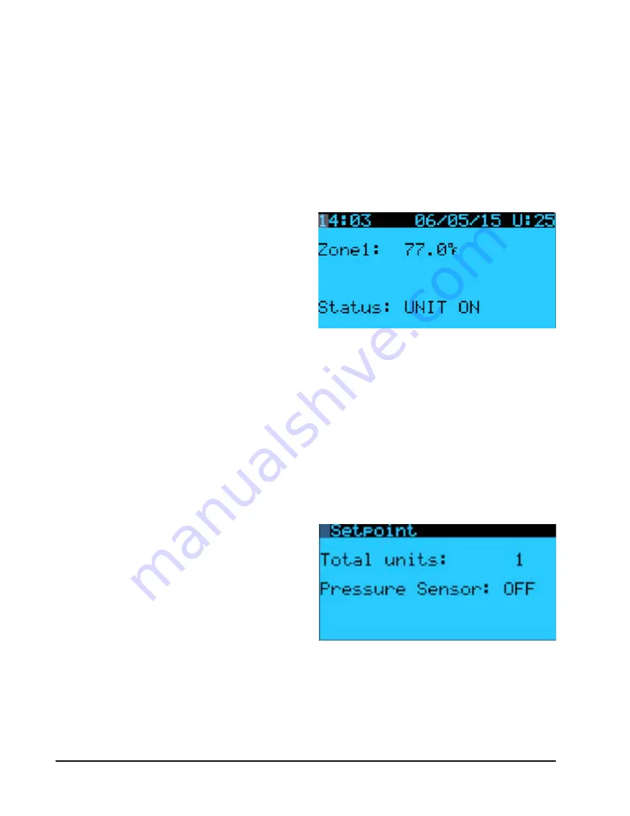
FIGURE 2.7
Controller Status Display
* Option to enable humidifier
Verifying Communication to Units
Check controller display to see that all units are
"online". If all units are online, the display will appear
as shown in Figure 2.9. If any of the units are not
online, the display will appear as shown in Figure 2.10.
To determine which unit or units are offline:
FIGURE 2.8
Total Units Displayed
Содержание W48A2PQ
Страница 6: ...Manual 2100 642 Page 6 of 82...
Страница 7: ...Manual 2100 642 Page 7 of 82 SECTION 1 INSTALLATION INSTRUCTIONS...
Страница 35: ...Manual 2100 642 Page 35 of 82 SECTION 2 SERVICE INSTRUCTIONS...
Страница 62: ...Manual 2100 642 Page 62 of 82...
Страница 63: ...Manual 2100 642 Page 63 of 82 SECTION 3 APPENDIX...


