Manual 2100-642
Page
31 of 82
SYSTEM START-UP
The Bard-Link
TM
controller and TEC-EYE hand-
held diagnostic tool will both be used to set up the
controller and wall-mount units (see Figure 1.24 on
page 32). The TEC-EYE diagnostic tool is shipped
inside the controller.
1. Set Controller Date and Time
1) Shut down all breakers to wall-mount units
and the Bard-Link
TM
controller.
2) Restore AC power to the wall-mount units.
3) Turn on power to the Bard-Link
TM
controller.
There is a forty (40) second delay prior to
any function (other than display backlight)
becoming active. The Status screen is the
default screen when the controller has power.
4) Access the controller Main Menu by pressing
the Menu key.
5) Press the UP or DOWN keys to scroll to the
Clock/Scheduler menu. Press the ENTER key
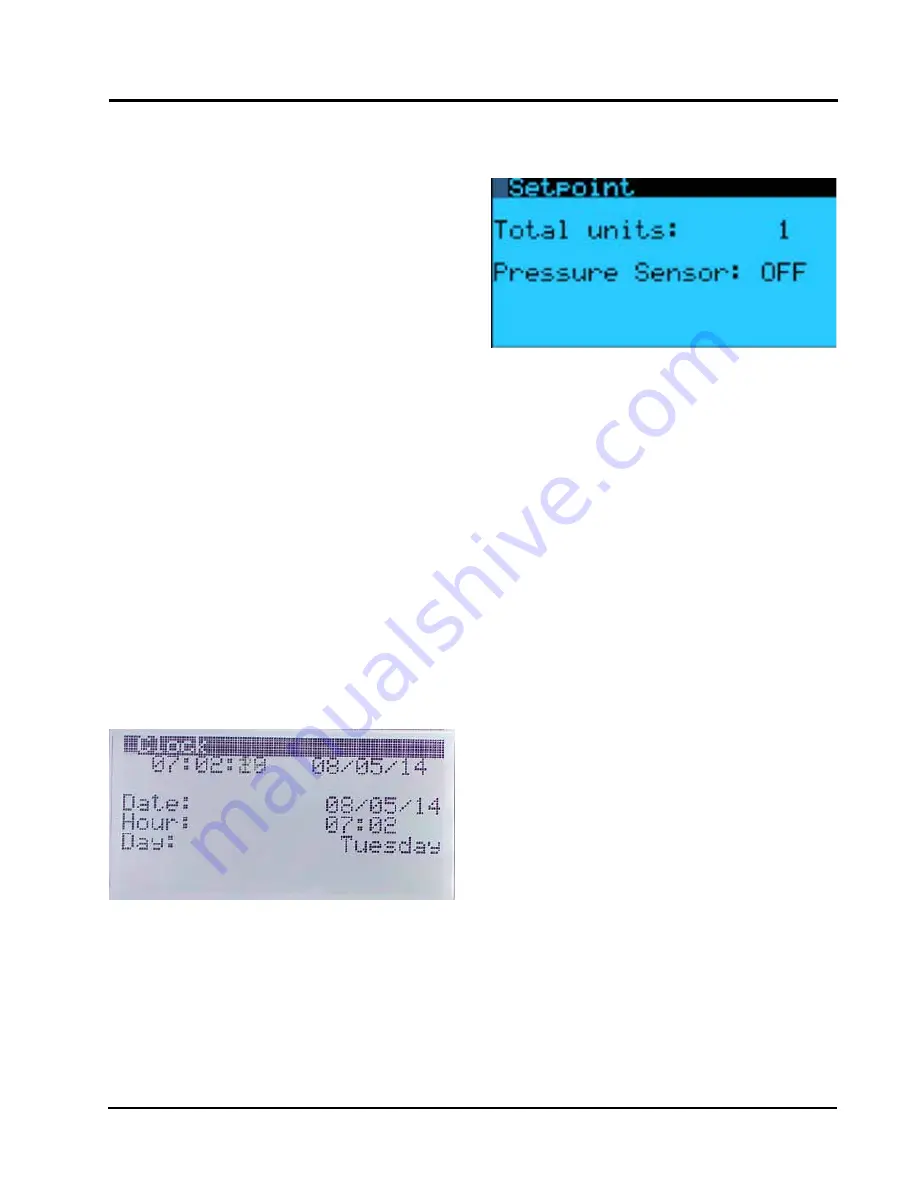
(see Figure 1.22).
6)
Move the cursor to the Date line by pressing
the ENTER key. Press the UP or DOWN keys to
change the date. The Day line will automatically
change when the date has been altered.
7) Press the ENTER key to move to the Hour line.
Press the UP or DOWN keys to change the
time. Press the ENTER key to set the time.
8) Press the ESCAPE several times to return to
the Status menu.
FIGURE 1.22
Clock/Scheduler Menu
2. Enter Total Units
1) On LC controller, go to Technician menu and
press ENTER key.
2) Go to Unit Set Up menu, press ENTER key.
3) Press ENTER key to move cursor to Total
Units. Use the UP arrow key to change unit
count to the number of units that will be
connected to the LC controller (see Figure
1.23).
FIGURE 1.23
Total Units Displayed
3. Set Up and Configure Units
Set up and configuration must be done to each
unit using the TEC-EYE hand-held diagnostic tool.
1) Remove communication wire connection plug
from wall unit control board (see page 39).
2) On the TEC-EYE, go to Technician menu, press
ENTER key.
3) Go to Unit Set Up menu, press ENTER key.
4) Use the ENTER key to select the zone number
(1, 2 or 3) the unit will be utilized in to
condition the space. Press ENTER key.
5) Select mode of operation for the unit. The
options are Active, Standby, Active Locked and
Standby Locked.
Active: When mode is set to Active, the unit
will be available to cool the space.
Standby: When mode is set to Standby, the
unit is available for rotation or if an alarm is
activated on an Active mode unit.
Active Locked: When mode is set to Active
Locked, the unit is not available for rotation
Standby Locked: When mode is set to Standby
Locked, the unit is not available for rotation
but is available to come on if an alarm is
activated on Active mode units.
6) Set unit address: This address must be unique
for each unit to be recognized on the network.
Set the address to 1-12 and press the ENTER
key.
7) Set cool stage option: Options are 1 for units
with a single stage compressor (comes on
100% when call for mechanical cooling) or 2
for units with a two stage compressor (comes
on at part load initially and increases to 100%
capacity). Select and set for 1 or 2 and press
ENTER key.
Содержание W48A2PQ
Страница 6: ...Manual 2100 642 Page 6 of 82...
Страница 7: ...Manual 2100 642 Page 7 of 82 SECTION 1 INSTALLATION INSTRUCTIONS...
Страница 35: ...Manual 2100 642 Page 35 of 82 SECTION 2 SERVICE INSTRUCTIONS...
Страница 62: ...Manual 2100 642 Page 62 of 82...
Страница 63: ...Manual 2100 642 Page 63 of 82 SECTION 3 APPENDIX...


