Manual 2100-676B
Page
83 of 88
Setting Up LC6000 for Operation
The LC6000 controller will be used for the remaining
steps in the set up process.
LC6000 Status Screen
The Status screen is the default start-up screen and
also the return screen after 5 minutes of no activity on
the LC6000. The screen can be accessed any time by
pressing the ESCAPE key repeatedly.
3) Press UP or DOWN keys to scroll to
Settings
;
press ENTER key.
4) Press UP or DOWN keys to scroll to
Initialization
; press ENTER key.
5) Press ENTER key to scroll to
Clear Alarm
Logs?
(see Figure 41).
6) Press UP or DOWN key to value to
YES
; press
ENTER key.
7) Press ESCAPE key several times to return to
Main Menu screen.
After each of the wall-mount units have been
addressed, had a run test performed and had the alarm
logs cleared, the rest of the system set up can proceed.
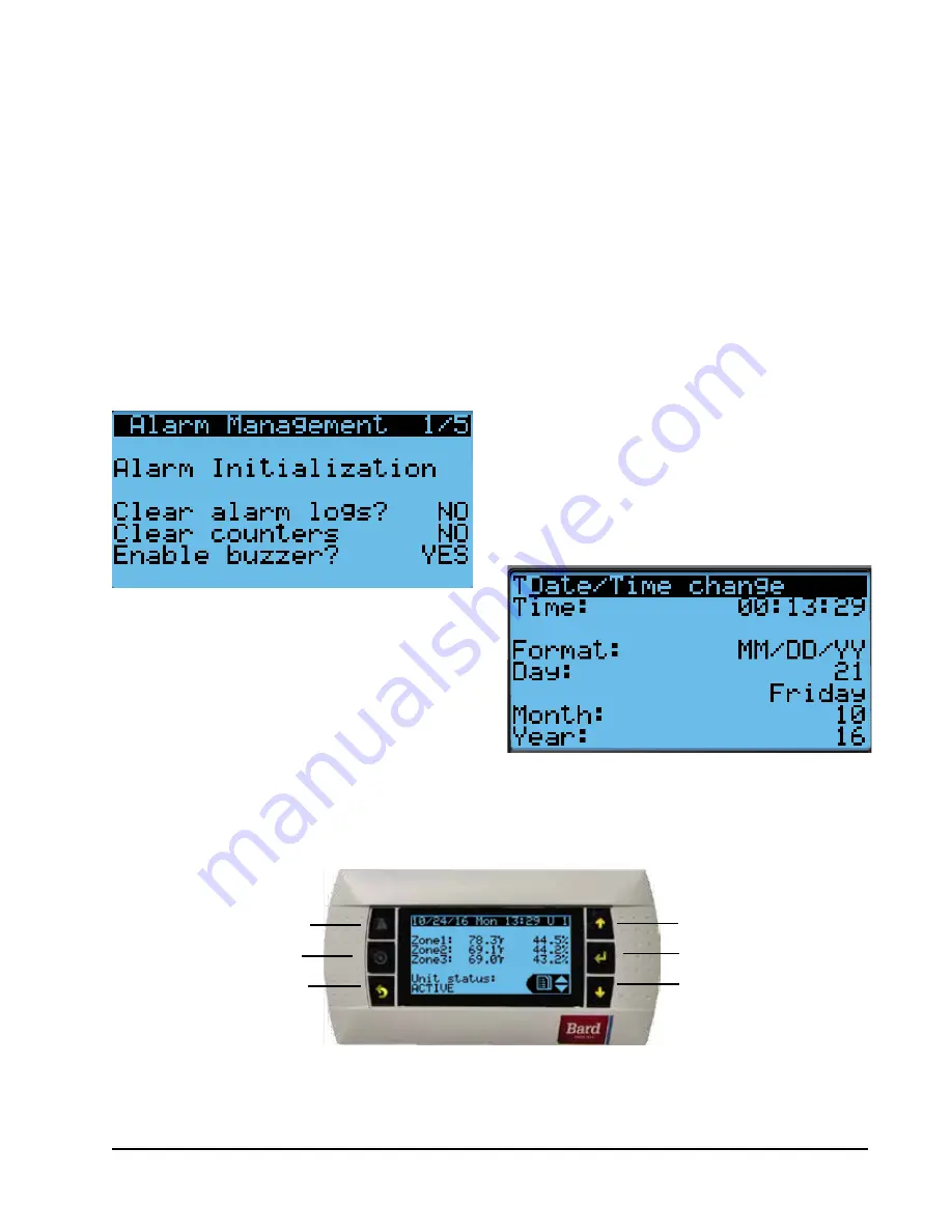
FIGURE 41
Clearing Unit Alarm Logs
The Status screen on the LC6000 displays the current
date, time, unit displayed, zones and unit status (see
Figure 43).
4. Set LC Controller Date and Time
1) Press MENU key to access the Main Menu
screen.
2) Use UP or DOWN keys and ENTER key to
enter USER password 2000.
3) Press the UP or DOWN keys to scroll to the
Settings
menu; press ENTER key.
4) Press UP or DOWN keys to scroll to
Date/Time
menu; press ENTER key.
5) Press ENTER key to scroll to the desired value
to be changed (see Figure 42).
6) Press UP or DOWN keys to change the value.
7) Press ESCAPE key several times to return to
Main Menu screen.
NOTE:
The LC6000 will sync the time and date
configured to each of the wall-mount units once
communication is established.
FIGURE 42
Setting Controller Date and Time
DOWN KEY
ALARM KEY
MENU KEY
UP KEY
ENTER KEY
ESCAPE KEY
FIGURE 43
LC6000 Controller Display and Interface (Status Screen Shown)
LC6000 interface key functions are the same as those shown for the TEC-
EYE in Figure 34 on page 80.
Содержание MULTI-TEC W24AAPA
Страница 3: ...Page 3 of 88 SECTION 1 MULTI TEC LC6000 INSTALLATION INSTRUCTIONS...
Страница 36: ...Manual 2100 676B Page 36 of 88 FIGURE 25 LC6000 Wiring Diagram...
Страница 46: ...Manual 2100 676B Page 46 of 88...
Страница 47: ...Manual 2100 676B Page 47 of 88 SECTION 2 WR SERIES LC6000 INSTALLATION INSTRUCTIONS...
Страница 79: ...Manual 2100 676B Page 79 of 88 FIGURE 32 LC6000 Wiring Diagram...


