


13 Configuring Sensors
Each sensor type has a parameters shortcut menu available from the inspection menu.
From the Home screen, click inside the Region of Interest (ROI). The ROI is the visual area indicated by a dotted line on the
inspection. In the Demo mode this is the Banner Engineering logo. The dotted line becomes bold and has rotation and size
icons in the corners. At the top of the display
Inspection Name
changes to a black button called
Sensor Name
. Click Sensor
Name and a dropdown list displays.
Figure 98. Example Shortcut Menu
No matter what parameter you are setting, if you click inside the ROI it will highlight into a bold dotted line that can be
resized.
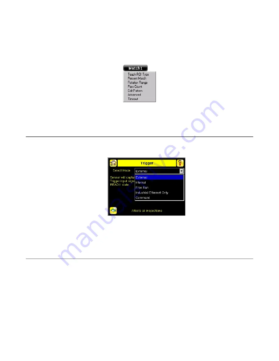
13.1 Setting the Trigger
By default, the Trigger is set to Internal, and will continuously trigger based on a time interval setting. This may make it more
difficult to make adjustments while setting up the iVu. The best practice is:
1. Go to Main Menu > Imager > Trigger menu and select External.
Figure 99. Trigger Screen
2. Make sure there is no external trigger input.
3. Use the Trigger icon in the lower-right of the display to manually trigger the iVu to capture an image as you set up
and test.
4. Capture images of a range of samples to set up from the "worst" good part to the "best" bad part.
13.2 Configuring an Area Sensor
1. Begin the setup with a good part.
2. Center the part to be tested in the Field of View (FOV).
3. Adjust the Region of Interest (ROI) so that it surrounds the feature of interest. In the Demo example, the feature of
interest is the Banner logo. The ROI is red because the parameters need to be set.
iVu Plus TG and Color Gen2 Image Sensors
80
www.bannerengineering.com - Tel: + 1 888 373 6767


