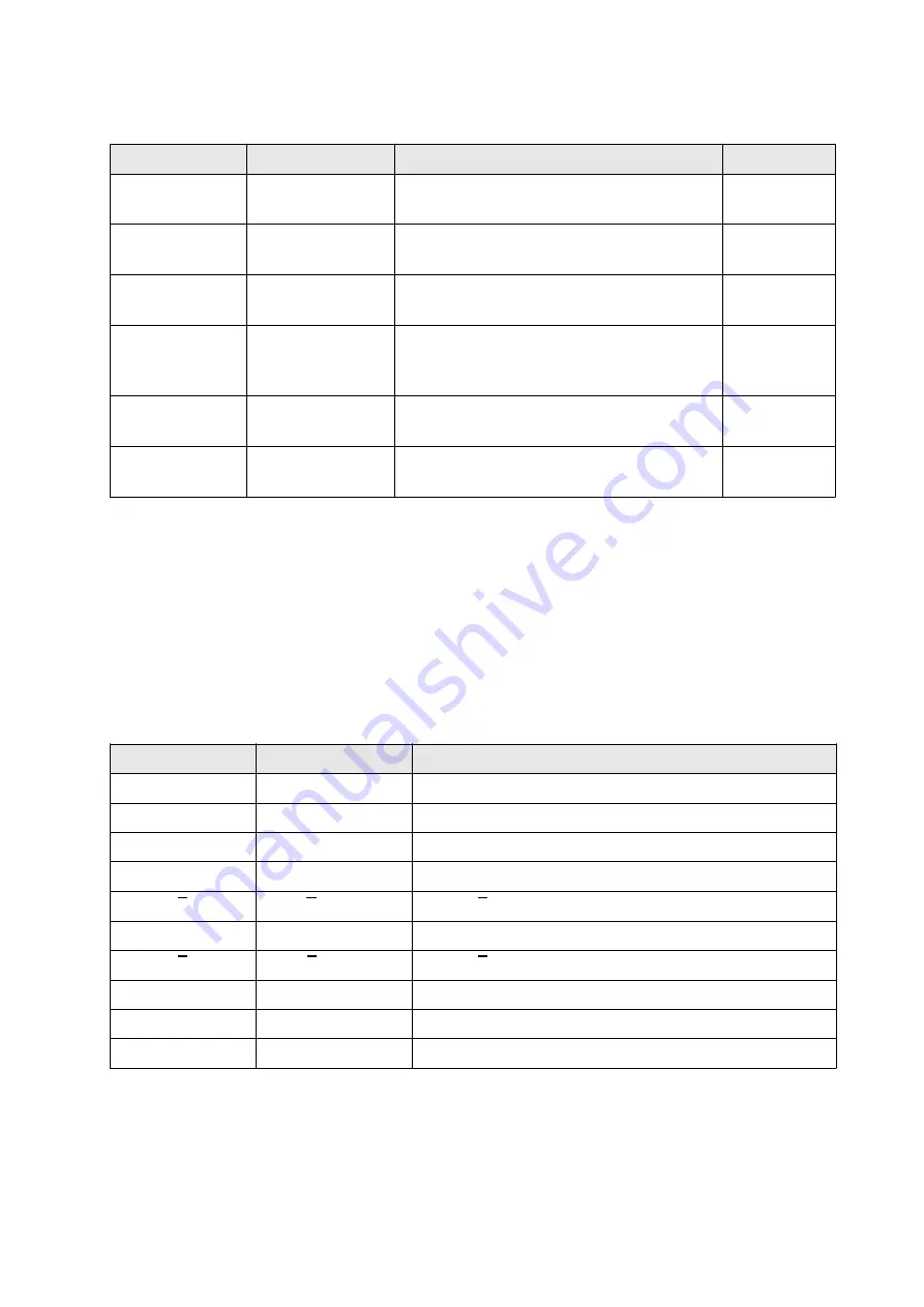
Table 4.3 Control Circuit Output Terminals
TERMINAL
FUNCTION
DEFINITION
CONTACTS
MC1 - MC4
(COM - NO)
Auxiliary Relay of
Motor Contactor
Switching relay of motor output contactors
(K1-K2).
250V AC/10A
30V DC/10A
BR1 - BR4
(COM - NO)
Auxiliary Relay of
Brake Contactor
Switching relay of brake contactor (KF).
250V AC/10A
30V DC/10A
ER1 – ER2 - ER4
(COM - NC - NO)
Fault Relay
Sends fault signal.
250V AC/10A
30V DC/10A
DB1 - DB4
(COM - NO)
Door Bridging
Speed Relay
Output of preopening door function. Sends
signal when the driver speeds is lower than
the parameter [S20] in stopping phase.
250V AC/3A
30V DC/3A
O11 - O14
(COM - NO)
Programmable
Output O1
Programmable Relay Output 1
(Detailed information is in Section 8.6)
250V AC/3A
30V DC/3A
O21 - O24
(COM - NO)
Programmable
Output O2
Programmable Relay Output 2
(Detailed information is in Section 8.6)
250V AC/3A
30V DC/3A
4.7 ENCODER TERMINALS
4.7.1 Asynchronous Motor
Connections of encoder cable to the terminals have to be established in closed loop control. Terminals of
encoder placed at the right side of the device. Incremental encoder connection is listed in Table 4.4. Be
sure to set ppr value of the encoder to [M10] properly. Connection diagrams of mostly used encoders
are shown in Figure 4.8 and connection between simulation outputs of device and control panel diagram
is in Figure 4.9.
Table 4.4 Incremental Encoder Terminals
TERMINAL
FUNCTION
DEFINITION
GND
0V DC Supply
Common of supply voltage (0V/GND)
15V
+15V DC Supply
Supply voltage (HTL encoder)
5V
+5V DC Supply
Supply voltage (TTL enkoder)
A
A Phase
Encoder A phase signal input
A
A Phase
Encoder A phase signal input
B
B Phase
Encoder B phase signal input
B
B Phase
Encoder B phase signal input
OA
Simulation A Phase
Encoder simulation output A phase
OB
Simulation B Phase
Encoder simulation output B phase
PE
Earth
Encoder earth (cable screening) screw
F/7.5.5.02.95 R:1
11
AE-LIFT


