AXELL D-MBR 3007-3008-PS NFPA REPEATER
PRODUCT DESCRIPTION AND USER’S MANUAL
24
UMCD00013 Rev 2.2
© Axell Wireless Ltd
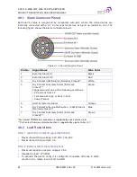
3.9.1 Alarm Connector Pinout
Each alarm status is recognized by a separate wire-pair, where the colored wires are
internally connected with a 4.7 K ohm resistor (serves as a pull up resistor to +5V
.
The
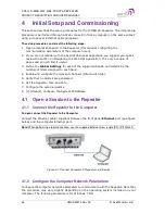
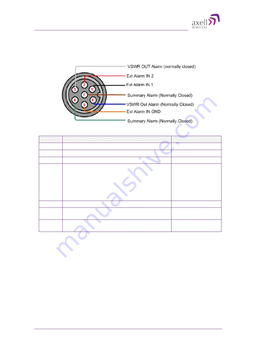
following figure shows the Alarm connector pinout.
Figure 3-11. Alarm Connector Pinout
Pin No.
Signal Name
Wire Color
1
External Alarm #1
Black
2
External Alarm #2
Red
3
Dry Contact VSWR Alarm (Normally Closed)*
White
4
Dry Contact Summary Alarm (Normally
Closed)**
Triggered under one of the following conditions:
•
PA Current from FF
•
Temperature High or Built in Test
•
Power Failure
Green
5
GND for External Alarm
Orange
6
Dry Contact Antenna Malfunction (VSWR) Alarm
(Normally Closed)*
Blue
7
Dry Contact Summary Alarm (Normally
Closed)**
Brown
*Dry Contact VSWR alarm connection is supported by a pair of wires (3,6).
** Dry Contact Summary alarm connection is supported by a pair of wires (4,7)
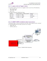
3.9.2 Load Restrictions
3.9.2.1 Alarm Dry Contact Output Restrictions
•
Maximum switching voltage: 220 VDC, 125 VAC
•
Maximum switching current: 2A
3.9.2.2 External Alarm Input Restrictions
•
Maximum repetitive reverse voltage: 28 V
•
Impedance load: 470 Ohm
•
To activate the alarm: verify it is configured to operate normally in LOW
(section 4.4), where low is short to GND.

