Axell D-MBR 3007-3008-PS-NFPA
PRODUCT DESCRIPTION AND USER’S MANUAL
© Axell Wireless Ltd
UMCD00013 Rev 2.2
23
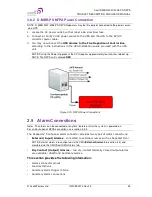
3.8.2 D-MBR-PS NFPA Power Connection
NOTE: D-MBR 3007-3008-PS NFPA Repeaters may be (if required) connected to the power source
via a UPS.
1. Locate the AC power outlet, with at least a 6A slow blow fuse.
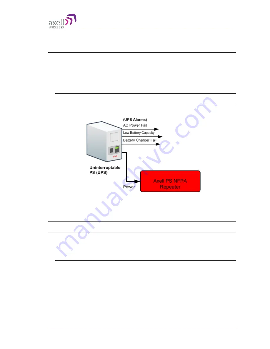
2. Connect a 110/220 VAC power source to the UPS and the UPS to the AC/DC
converter power cable.
3. You may now connect the
UPS alarms to the Fire Department Control Box
according to the instructions in the UPS Installation Guide provided with the UPS
unit.
NOTE: During the Power Up process the CPU requires approximately four minutes to boot up.
NOTE: The NFPA unit is colored
RED
.
Figure 3-10. NFPA Power Connections
3.9 Alarm Connections
Notes: The alarms can be connected at any time, before or after the system is powered-on.
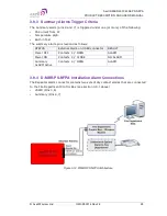
For an illustration of NFPA connections, see section 3.9.4.
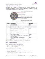
The Repeaters’ front panel Alarm connector provides two types of alarm connections:
•
External (Input) Alarms
- connected to external sources such as Repeater Door .
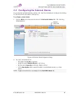
NOTE: External alarms are configured via the CMU/
External Alarms
tab (section 4.4) and
monitored via the CMU/Axell-CMU-Alarms tab.
•
Dry Contact (Output) Alarms
– two dry-contact
Normally Closed
output alarms
are available: VSWR and Summary alarms.
This section provides the following information:
•
Alarms connector pinout
•
Load restrictions
•
Summary alarm trigger criteria
•
Summary alarm connections

