PAGE
132
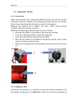
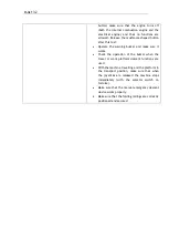
button; make sure that the engine turns off
(both the internal combustion engine and the
electrical engine) and that no functions are
allowed. Release the mushroom-shaped button
after this test.
•
Operate the warning buzzer and make sure it
works.
•
Check the operation of the buzzer when the
travel or work platform descent functions are
used.
•
With the machine travelling and the platform in
the transport position, make sure that when
the joysticks are released the machine stops
immediately (with the selector switch on
tortoise).
•
Make sure that the manual emergency descent
device works properly.
•
Make sure that the folding railings are correctly
positioned and secured
Содержание 1470-HE EVO
Страница 7: ...PAGE 7...
Страница 12: ...PAGE 12 Work area on tracks Travel not allowed Maximum inclination allowed 2 5020 5490 7500...
Страница 27: ...PAGE 27...
Страница 28: ...PAGE 28...
Страница 34: ...PAGE 34 Warning Do not tighten the fixing belts too much so as not to damage the eye bolts...
Страница 50: ...PAGE 50 8 Extendible basket pedal...
Страница 57: ...PAGE 57 38 Chassis and stabilisers...
Страница 74: ...PAGE 74...
Страница 76: ...PAGE 76...
Страница 77: ...PAGE 77...
Страница 80: ...PAGE 80...
Страница 87: ...PAGE 87 Attention IT IS FORBIDDEN to block the gate in such a way as to keep access to the platform open...
Страница 137: ...PAGE 137 In this configuration the oil level B must be at a distance of 30mm from the maximum level C...
Страница 138: ...PAGE 138...
Страница 160: ...PAGE 160...
Страница 161: ...PAGE 161...
Страница 162: ...PAGE 162...
Страница 163: ...PAGE 163...
Страница 164: ...PAGE 164...
Страница 165: ...PAGE 165...
Страница 166: ...PAGE 166...
Страница 167: ...PAGE 167...
Страница 168: ...PAGE 168...
Страница 172: ...PAGE 172 6 Using the nut supplied point A 7 Move the front wheel back by pressing on the track with your foot...
Страница 178: ...PAGE 178 MANDATORY ROUTINE INSPECTIONS Date Observations Seal Signature...
Страница 191: ...PAGE 191 8 4 Hydraulic diagram See attachment 8 5 Wiring diagram See attachment...

