


PAGE
130
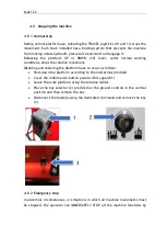
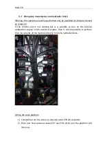
6.1.2
Checks before each use
Prior to commissioning and before each use the machine must undergo the visual
and functional checks given below.
The instructions given below must be followed.
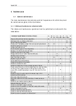
VISUAL CHECK
CHECK OPERATION
•
Visually check under and around the
machine to make sure that there are no
oil or fuel leaks.
•
Make sure that there is no hydraulic oil
leaking from the hoses and from the
other
components
(cylinders,
distributors, fittings, etc.).
•
Check that there are no cut or worn
electrical
cables
and
that
the
connectors are correctly secured.
•
Check the fuel level before starting so
as to prevent interruptions while
working.
•
Check the engine oil level.
•
Check the hydraulic oil level.
•
Make sure that none of the screws,
bolts or ferrules are loose or missing.
•
Make sure that all the "Seeger" safety
rings are present and correctly in place
with there washers.
•
Make sure that all the pins are in place
and correctly secured.
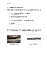
•
Make sure the tracks are not cut or
abnormally worn
•
Always check to make sure that track
tension is correct
•
Check, and if necessary grease, the
scissor runners, both those in contact
with the platform and those in contact
with the lower frame.
•
Check that the manual, the plates and
the stickers are on the machine.
•
Check that the steel structure is not
deformed.
•
Make sure there are no cracks in the
welds, damage or abnormal wear
•
Make sure that the 12V internal
combustion engine ignition battery is
•
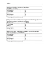
With
the
platform
in
the
transport
configuration, place the machine without
lowering the stabilisers with the frame tilted
with respect to the horizontal by a value
greater than 2° on the lateral. Operate the
platform lifting control and make sure that it is
not possible to raise the platform.
•
With
the
platform
in
the
transport
configuration, place the machine without
lowering the stabilisers with the frame tilted
with respect to the horizontal by a value
greater than 2° on the longitudinal. Operate
the platform lifting control and make sure that
it is not possible to raise the platform.
•
With
the
platform
in
the
transport
configuration, lower the stabilisers by means of
the automatic stabilisation selector switch.
Make sure that the tracks are raised from the
ground and that the machine levels within 0.5°.
A horn will warn the operator that the frame is
within the 0.5° of inclination. At the end of
this procedure, make sure that it is possible to
lift the work platform using the up control.
•
Lift the platform without a load to the
maximum height and then lower it a few times;
make sure that the machine works correctly
•
Check the operation of the anti-shearing
device. This can be done by lifting the work
platform to a height of about 2 metres above
the transport height. It is necessary to check
that
the
downward
movement
stops
automatically at a height such that the vertical
distance between the ends of the scissors must
be greater than 50mm. Further movements
downwards are possible only after a 3s delay at
reduced speed.
•
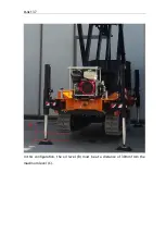
With the machine stabilised on the tracks,
check the operation of the travel function with
Содержание 1470-HE EVO
Страница 7: ...PAGE 7...
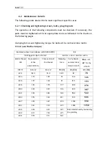
Страница 12: ...PAGE 12 Work area on tracks Travel not allowed Maximum inclination allowed 2 5020 5490 7500...
Страница 27: ...PAGE 27...
Страница 28: ...PAGE 28...
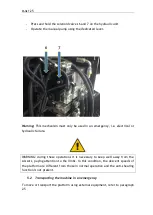
Страница 34: ...PAGE 34 Warning Do not tighten the fixing belts too much so as not to damage the eye bolts...
Страница 50: ...PAGE 50 8 Extendible basket pedal...
Страница 57: ...PAGE 57 38 Chassis and stabilisers...
Страница 74: ...PAGE 74...
Страница 76: ...PAGE 76...
Страница 77: ...PAGE 77...
Страница 80: ...PAGE 80...
Страница 87: ...PAGE 87 Attention IT IS FORBIDDEN to block the gate in such a way as to keep access to the platform open...
Страница 137: ...PAGE 137 In this configuration the oil level B must be at a distance of 30mm from the maximum level C...
Страница 138: ...PAGE 138...
Страница 160: ...PAGE 160...
Страница 161: ...PAGE 161...
Страница 162: ...PAGE 162...
Страница 163: ...PAGE 163...
Страница 164: ...PAGE 164...
Страница 165: ...PAGE 165...
Страница 166: ...PAGE 166...
Страница 167: ...PAGE 167...
Страница 168: ...PAGE 168...
Страница 172: ...PAGE 172 6 Using the nut supplied point A 7 Move the front wheel back by pressing on the track with your foot...
Страница 178: ...PAGE 178 MANDATORY ROUTINE INSPECTIONS Date Observations Seal Signature...
Страница 191: ...PAGE 191 8 4 Hydraulic diagram See attachment 8 5 Wiring diagram See attachment...