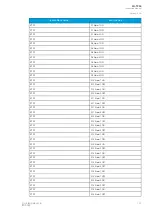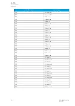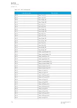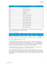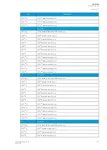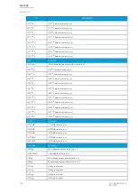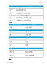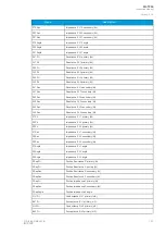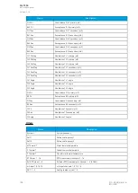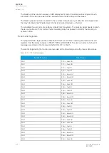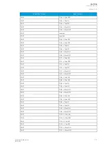
Event block name
Event names
ARC1
Channel 4 Light OFF
ARC1
Channel 4 Pressure ON
ARC1
Channel 4 Pressure OFF
ARC1
DI Signal ON
ARC1
DI Signal OFF
ARC1
I/I0 Arc> Sensor 1 Fault ON
ARC1
I/I0 Arc> Sensor 1 Fault OFF
ARC1
I/I0 Arc> Sensor 2 Fault ON
ARC1
I/I0 Arc> Sensor 2 Fault OFF
ARC1
I/I0 Arc> Sensor 3 Fault ON
ARC1
I/I0 Arc> Sensor 3 Fault OFF
ARC1
I/I0 Arc> Sensor 4 Fault ON
ARC1
I/I0 Arc> Sensor 4 Fault OFF
ARC1
I/I0 Arc> I/O-unit Fault ON
ARC1
I/I0 Arc> I/O-unit Fault OFF
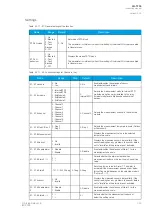
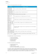
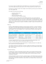
The function registers its operation into the last twelve (12) time-stamped registers. The table below
presents the structure of the function's register content.
Table. 5.3.12 - 99. Register content.
Date and time
Event
Phase A
current
Phase B
current
Phase C
current
Residual
current
Active
sensors
Used SG
dd.mm.yyyy
hh:mm:ss.mss
Event
name
Trip current
Trip current
Trip current
Trip current
1...4
Setting group
1...8 active
5.3.13 Programmable stage (PGx>/<; 99)
The programmable stage is a stage that the user can program to create more advanced applications,
either as an individual stage or together with programmable logic. The relay has ten programmable
stages, and each can be set to follow one to three analog measurements. The programmable stages
have three available pick up terms options: overX, underX and rate-of-change of the selected signal.
Each stage includes a definite time delay to trip after a pick-up has been triggered.
The programmable stage cycle time is 5 ms. The pick-up delay depends on which analog signal is
used as well as its refresh rate (typically under a cycle in a 50 Hz system).
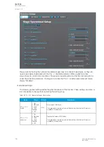
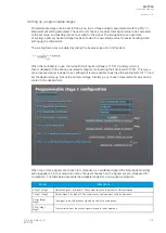
The number of programmable stages to be used is set in the
INFO tab. When this function has been
set as "Activated", the number of programmable stages can be set anywhere between one (1) and ten
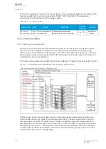
(10) depending on how many the application needs. In the image below, the number of programmable
stages have been set to two which makes PS1 and PS2 to appear. Inactive stages are hidden until they
are activated.
A
AQ
Q-T256
-T256
Instruction manual
Version: 2.06
© Arcteq Relays Ltd
IM00028
157
Содержание AQ-T256
Страница 1: ...AQ T256 Transformer protection IED Instruction manual...
Страница 2: ......
Страница 264: ...Figure 7 3 120 Example block scheme A AQ Q T256 T256 Instruction manual Version 2 06 262 Arcteq Relays Ltd IM00028...
Страница 284: ...Figure 8 13 141 Device installation A AQ Q T256 T256 Instruction manual Version 2 06 282 Arcteq Relays Ltd IM00028...

