5.5.6 Measurement value recorder
The measurement value recorder function records the value of the selected magnitudes at the time of a
pre-defined trigger signal. An typical application is the recording of fault currents or voltages at the time
of the breaker trips; it can also be used to record the values from any trigger signal set by the user. The
user can select whether the function records per-unit values or primary values. Additionally, the user
can set the function to record overcurrent fault types or voltage fault types. The function operates
instantly from the trigger signal.
The measurement value recorder function has an integrated fault display which shows the current fault
values when the tripped by one of the following functions: I> (non-directional overcurrent), Idir>
(directional overcurrent), I0> (non-directional earth fault), I0dir> (directional earth fault), f<
(underfrequency), f> (overfrequency), U< (undervoltage), U> (overvoltage), U1/U2 >/< (sequence
voltage) or U0> (residual voltage). When any of these functions trip, the fault values and the fault type
are displayed in the Mimic view. The view can be enabled by activating the "VREC Trigger
on"setting (
Tools
→
Events and logs
→
Set alarm events). The resetting of the fault values is done by
the input selected in the
General menu.
Measured input
The function block uses analog current and voltage measurement values. Based on these values, the
relay calculates the primary and secondary values of currents, voltages, powers, and impedances as
well as other values.
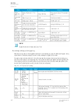
The user can set up to eight (8) magnitudes to be recorded when the function is triggered. An
overcurrent fault type, a voltage fault type, and a tripped stage can be recorded and reported straight
to SCADA.
NO
NOTE!
TE!
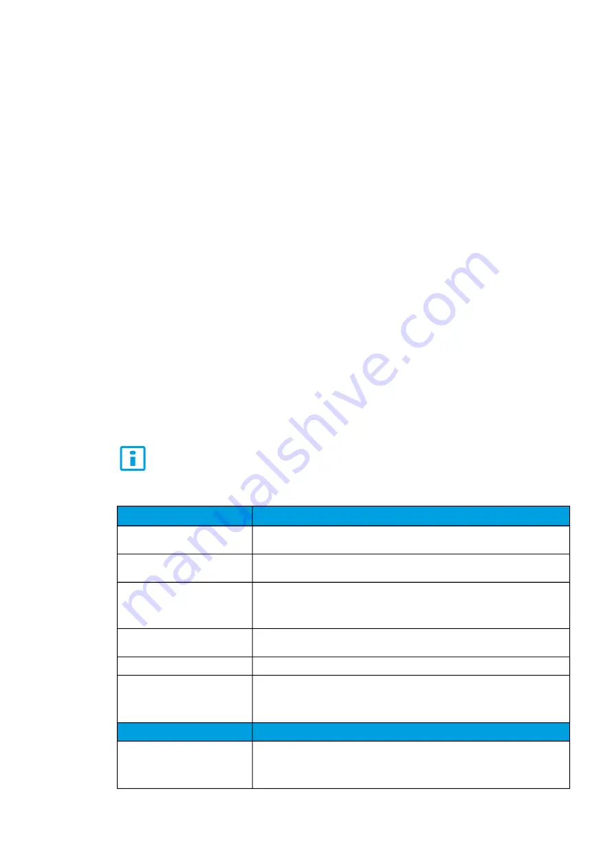
The available measurement values depend on the relay type. If only current analog
measurements are available, the recorder can solely use signals which only use current. The
same applies, if only voltage analog measurements are available.
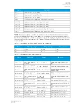
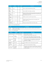
Currents
Description
IL1 (ff), IL2 (ff), IL3 (ff), I01 (ff), I02
(ff)
The fundamental frequency current measurement values (RMS) of phase currents and
of residual currents.
IL1TRMS, IL2TRMS, IL3TRMS,
I01TRMS, I02TRMS
The TRMS current measurement values of phase currents and of residual currents.
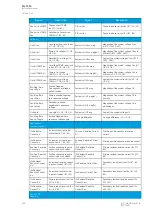
IL1,2,3 & I01/I02 2
nd
h., 3
rd
h., 4
th
h., 5
th
h., 7
th
h., 9
th
h., 11
th
h., 13
th
h., 15
th
h., 17
th
h., 19
th
h.
The magnitudes of phase current components: Fundamental, 2
nd
harmonic, 3
rd
harmonic, 4
th
harmonic, 5
th
harmonic 7
th
, harmonic 9
th
, harmonic 11
th
, harmonic 13
th
,
harmonic 15
th
, harmonic 17
th
, harmonic 19
th
harmonic current.
I1, I2, I0Z
The positive sequence current, the negative sequence current and the zero sequence
current.
I0CalcMag
The residual current calculated from phase currents.
IL1Ang, IL2Ang, IL3Ang,
I01Ang, I02Ang, I0CalcAng,
I1Ang, I2Ang
The angles of each measured current.
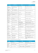
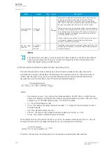
VVolta
oltages
ges
Descrip
Description
tion
UL1Mag, UL2Mag, UL3Mag,
UL12Mag, UL23Mag, UL31Mag
U0Mag, U0CalcMag
The magnitudes of phase voltages, of phase-to-phase voltages, and of residual
voltages.
A
AQ
Q-T256
-T256
Instruction manual
Version: 2.06
© Arcteq Relays Ltd
IM00028
239
Содержание AQ-T256
Страница 1: ...AQ T256 Transformer protection IED Instruction manual...
Страница 2: ......
Страница 264: ...Figure 7 3 120 Example block scheme A AQ Q T256 T256 Instruction manual Version 2 06 262 Arcteq Relays Ltd IM00028...
Страница 284: ...Figure 8 13 141 Device installation A AQ Q T256 T256 Instruction manual Version 2 06 282 Arcteq Relays Ltd IM00028...

