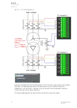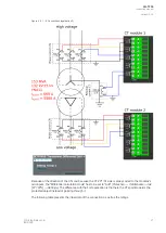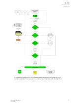
Figure. 5.2.1 - 4. Connections (application 1).
Because of the direction of the CTs and because the CTs' P1/S1 side is always wired to the modules's
odd inputs, the "Differential calculation mode" setting has to be set to "Subtract" (
Protection
→
TrafoModule
→
Idx> [87T,87N]
→
Settings). This way the direction of the measured currents are
checked correctly from the relay's perspective.
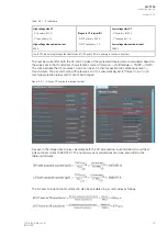
The following table presents the initial data of the connection as well as the ratings.
A
AQ
Q-T256
-T256
Instruction manual
Version: 2.06
18
© Arcteq Relays Ltd
IM00028
Содержание AQ-T256
Страница 1: ...AQ T256 Transformer protection IED Instruction manual...
Страница 2: ......
Страница 264: ...Figure 7 3 120 Example block scheme A AQ Q T256 T256 Instruction manual Version 2 06 262 Arcteq Relays Ltd IM00028...
Страница 284: ...Figure 8 13 141 Device installation A AQ Q T256 T256 Instruction manual Version 2 06 282 Arcteq Relays Ltd IM00028...


