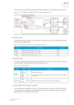
Figure. 5.4.8 - 91. Operation of logical input in "Hold" and "Pulse" modes.
A logical input pulse can also be extended by connecting a DELAY-low gate to a logical output, as has
been done in the example figure below.
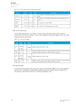
Figure. 5.4.8 - 92. Extending a logical input pulse.
Logical input descriptions
Logical outputs can be given a description. The description will be displayed in several of the menus
(logic editor, matrix, block settings etc.).
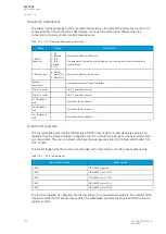
Table. 5.4.8 - 126. Logical input user description.
Name
Range
Default
Description
User editable
description LIx
1...31
characters
Logical
input x
Description of the logical input. This description is used in several menu
types for easier identification.
5.5 Monitoring functions
5.5.1 Current transformer supervision
The current transformer supervision function (abbreviated CTS in this document) is used for monitoring
the CTs as well as the wirings between the device and the CT inputs for malfunctions and wire breaks.
An open CT circuit can generate dangerously high voltages into the CT secondary side, and
cause unintended activations of current balance monitoring functions.
A
AQ
Q-T256
-T256
Instruction manual
Version: 2.06
© Arcteq Relays Ltd
IM00028
203
Содержание AQ-T256
Страница 1: ...AQ T256 Transformer protection IED Instruction manual...
Страница 2: ......
Страница 264: ...Figure 7 3 120 Example block scheme A AQ Q T256 T256 Instruction manual Version 2 06 262 Arcteq Relays Ltd IM00028...
Страница 284: ...Figure 8 13 141 Device installation A AQ Q T256 T256 Instruction manual Version 2 06 282 Arcteq Relays Ltd IM00028...


