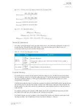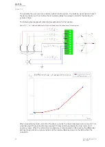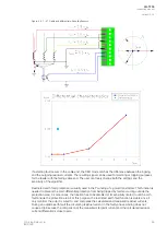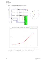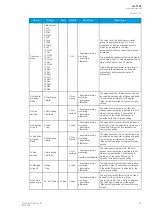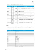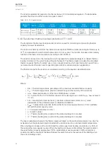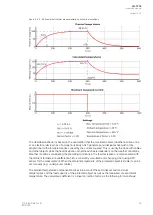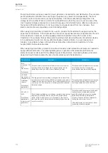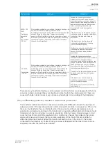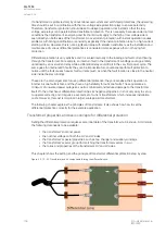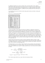
The function's outputs are TRIP and BLOCKED signals. The overvoltage function uses a total of eight
(8) separate setting groups which can be selected from one common source. Additionally, the
function's operating mode can be changed via the setting group selection.
The operational logic consists of the following:
• input magnitude processing
• thermal replica
• comparator
• block signal check
• output processing.
The inputs for the function are the following:
• setting parameters
• measured and pre-processed current magnitudes.
The function's output signals can be used for direct I/O controlling and user logic programming. The
function generates general time-stamped ON/OFF events to the common event buffer from each of the
two (2) output signal. The time stamp resolution is 1 ms. The function also provides a resettable
cumulative counter for the TRIP, ALARM 1, ALARM 2, INHIBIT and BLOCKED events.
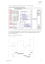
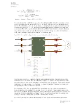
The following figure presents a simplified function block diagram of the transformer thermal overload
protection function.
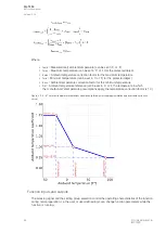
Figure. 5.3.9 - 48. Simplified function block diagram of the TT> function.
Measured input
The function block uses analog phase current measurement values. The function block uses TRMS
values from the whole harmonic specter of 32 components.
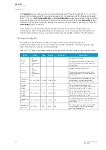
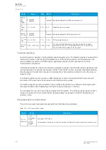
Table. 5.3.9 - 75. Measurement inputs of the TT> function.
Signal
Description
Time base
IL1TRMS
TRMS measurement of phase L1 (A) current
5 ms
IL2TRMS
TRMS measurement of phase L2 (B) current
5 ms
IL3TRMS
TRMS measurement of phase L3 (C) current
5 ms
RTD
Temperature measurement for the ambient correction
5 ms
A
AQ
Q-T256
-T256
Instruction manual
Version: 2.06
© Arcteq Relays Ltd
IM00028
97
Содержание AQ-T256
Страница 1: ...AQ T256 Transformer protection IED Instruction manual...
Страница 2: ......
Страница 264: ...Figure 7 3 120 Example block scheme A AQ Q T256 T256 Instruction manual Version 2 06 262 Arcteq Relays Ltd IM00028...
Страница 284: ...Figure 8 13 141 Device installation A AQ Q T256 T256 Instruction manual Version 2 06 282 Arcteq Relays Ltd IM00028...

