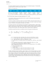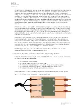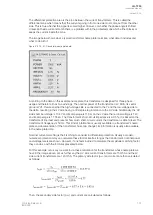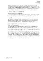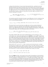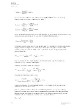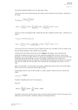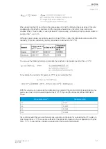
The calculations show that if 2 MVA of power go through the transformer the CT's secondary current
on the high-voltage side will be 3.85 A and the CT secondary current on the low-voltage side will be
4.81 A. The differential function uses these values to change them into measured currents in per unit.
Therefore, it would show 1.0 ·
I
n
for both HV and LV side measurements, eventhough the measured
currents are different. This is called amplitude matching of the HV and LV sides. In modern differential
relays this is done automatically when the nominal values and CT ratings are set for the transformer.
Thus, these calculations only have nice-to-know informational value.
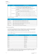
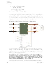
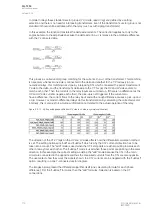
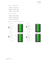
Figure. 5.3.10 - 52. Amplitude scaling to match the nominal currents and CTs in the differential relay.
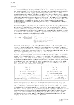
Nominal current matching is only part of the differential protection settings. The vector group of the
transformer is also important, since the differential function is interested in the angle difference of the
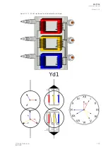
measured current vectors. In this example the transformer's vector group is Yd1, which means that the
transformer's HV side is connected to the Y and the LV side to the delta. Therefore, the LV side is in
30-degree lag in relation to the HV side vectors.
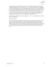
The number '1' in the vector group's name comes from the angle in the phase current difference
between the HV and the LV side. If one imagines the HV side current's Y placed upside down on the
face of a clock (with the Y's leg pointing at 12), the LV side's delta would be pointing at 1. Likewise, '11'
means that the LV side is leading 30 degrees; '5' and '7' are just the other ends of the windings thus
causing a 180-degree difference between the '1' and '11' clock numbers.
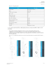
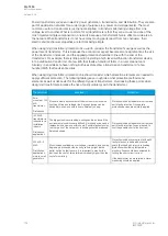
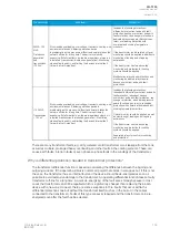
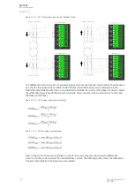
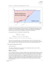
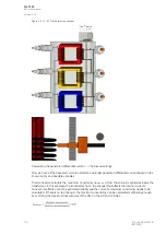
The following example explains transformer current vectors and what a connection might look like.
A
AQ
Q-T256
-T256
Instruction manual
Version: 2.06
108
© Arcteq Relays Ltd
IM00028
Содержание AQ-T256
Страница 1: ...AQ T256 Transformer protection IED Instruction manual...
Страница 2: ......
Страница 264: ...Figure 7 3 120 Example block scheme A AQ Q T256 T256 Instruction manual Version 2 06 262 Arcteq Relays Ltd IM00028...
Страница 284: ...Figure 8 13 141 Device installation A AQ Q T256 T256 Instruction manual Version 2 06 282 Arcteq Relays Ltd IM00028...

