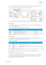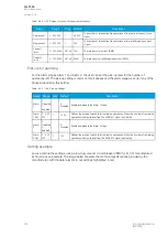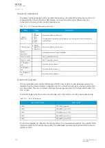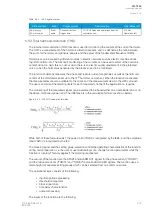
The recorder provides a great tool to analyze the performance of the power system during network
disturbance situations. The recorder's output is in general COMTRADE format and it is compatible with
most viewers and injection devices. The files are based on the IEEE standard C37.111-1999. Captured
recordings can be injected as playback with secondary testing tools that support the COMTRADE file
format. Playback of files might help to analyze the fault, or can be simply used for educational
purposes.
Analog and digital recording channels
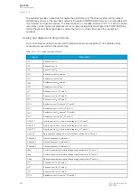
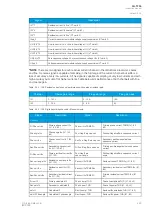
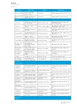
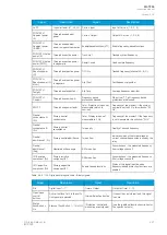
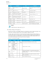
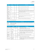
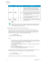
Up to 20 analog recording channels and 95 digital channels are supported. The available analog
channels vary according to the device type.
Table. 5.5.4 - 147. Analog recording channels.
Signal
Description
IL1
Phase current I
L1
IL2
Phase current I
L2
IL3
Phase current I
L3
I01c
Residual current I
01
coarse*
I01f
Residual current I
01
fine*
I02c
Residual current I
02
coarse*
I02f
Residual current I
02
fine*
IL1”
Phase current I
L1
(CT card 2)
IL2”
Phase current I
L2
(CT card 2)
IL3”
Phase current I
L3
(CT card 2)
I01”c
Residual current I
01
coarse* (CT card 2)
I01”f
Residual current I
01
fine* (CT card 2)
I02”c
Residual current I
02
coarse* (CT card 2)
I02”f
Residual current I
02
fine* (CT card 2)
U1(2)VT1
Line-to-neutral U
L1
or line-to-line voltage U
12
(VT card 1)
U2(3)VT1
Line-to-neutral U
L2
or line-to-line voltage U
23
(VT card 1)
U3(1)VT1
Line-to-neutral U
L3
or line-to-line voltage U
31
(VT card 1)
U0(ss)VT1
Zero sequence voltage U
0
or synchrocheck voltage U
SS
(VT card 1)
F tracked 1
Tracked frequency of reference 1
F tracked 2
Tracked frequency of reference 2
F tracked 3
Tracked frequency of reference 3
ISup
Current measurement module voltage supply supervision (CT card 1)
ISup''
Current measurement module voltage supply supervision (CT card 2)
USup
Voltage measurement module voltage supply supervision (VT card 2)
IL1'''
Phase current I
L1
(CT card 3)
IL2'''
Phase current I
L2
(CT card 3)
IL3'''
Phase current I
L3
(CT card 3)
I01'''c
Residual current I
01
coarse* (CT card 3)
A
AQ
Q-T256
-T256
Instruction manual
Version: 2.06
224
© Arcteq Relays Ltd
IM00028
Содержание AQ-T256
Страница 1: ...AQ T256 Transformer protection IED Instruction manual...
Страница 2: ......
Страница 264: ...Figure 7 3 120 Example block scheme A AQ Q T256 T256 Instruction manual Version 2 06 262 Arcteq Relays Ltd IM00028...
Страница 284: ...Figure 8 13 141 Device installation A AQ Q T256 T256 Instruction manual Version 2 06 282 Arcteq Relays Ltd IM00028...


