Settings
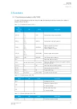
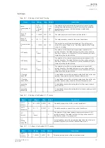
Table. 5.2.1 - 8. Settings of the Phase CT scaling.
Name
Unit
Range
Step Default
Description
Scale
measurement to
In
-
0: CT
nom p.u.
1: Object
In p.u.
-
0: CT
nom
p.u.
The selection of the reference used in the relay's per-unit system
scaling. Either the set phase current CT primary or the protected
object's nominal current. (NOT APPLICBLE IN MACHINE
PROTECTION!)
Phase CT
primary
A
1…25000 0.001 100
The rated primary current of the current transformer.
Phase CT
secondary
A
0.2…10
0.001 5
The rated secondary current of the current transformer.
Nominal current
In
A
1…25000 0.001 100
The nominal current of the protected object. This setting is only
visible if the option "Object In p.u." has been selected in the "Scale
meas. to In" setting.
IL1 Polarity
-
0: -
1: Invert
-
0: -
The selection of the first current measurement channel's (IL1)
polarity (direction). The default setting is for the positive current to
flow from connector 1 to connector 2, with the secondary currents'
starpoint pointing towards the line.
IL2 Polarity
-
0: -
1: Invert
-
0: -
The selection of the second current measurement channel's (IL2)
polarity (direction). The default setting is for the positive current to
flow from connector 3 to connector 4, with the secondary currents'
starpoint pointing towards the line.
IL3 Polarity
-
0: -
1: Invert
-
0: -
The selection of the third current measurement channel's (IL3)
polarity (direction). The default setting is for the positive current to
flow from connector 5 to connector 6, with the secondary currents'
starpoint pointing towards the line.
CT scaling
factor P/S
-
-
-
-
A relay feedback value; the calculated scaling factor that is the ratio
between the primary current and the secondary current.
CT scaling
factor NOM
-
-
-
-
A relay feedback value; the calculated scaling factor that is the ratio
between the set primary current and the set nominal current.
Ipu scaling
primary
-
-
-
-
A relay feedback value; the scaling factor for the primary current's
per-unit value.
Ipu scaling
secondary
-
-
-
-
A relay feedback value; the scaling factor for the secondary current's
per-unit value.
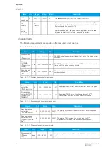
Table. 5.2.1 - 9. Settings of the Residual I01 CT scaling.
Name
Unit
Range
Step
Default
Description
I01 CT
primary
A
0.2…25000 0.00001 100
The rated primary current of the current transformer.
I01 CT
secondary A
0.1…10
0.00001 1.0
The rated secondary current of the current transformer.
I01
Polarity
-
0: -
1: Invert
-
0: -
The selection of the coarse residual measurement channel's (I01)
polarity (direction). The default setting is for the positive current to
flow from connector 7 to connector 8.
CT
scaling
factor P/S
-
-
-
-
A relay feedback value; the calculated scaling factor that is the ratio
between the primary current and the secondary current.
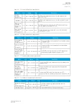
Table. 5.2.1 - 10. Settings of the Residual I02 CT scaling.
Name
Unit
Range
Step
Default
Description
I02 CT
primary
A
1…25000
0.00001 100
The rated primary current of the current transformer.
A
AQ
Q-T256
-T256
Instruction manual
Version: 2.06
© Arcteq Relays Ltd
IM00028
23
Содержание AQ-T256
Страница 1: ...AQ T256 Transformer protection IED Instruction manual...
Страница 2: ......
Страница 264: ...Figure 7 3 120 Example block scheme A AQ Q T256 T256 Instruction manual Version 2 06 262 Arcteq Relays Ltd IM00028...
Страница 284: ...Figure 8 13 141 Device installation A AQ Q T256 T256 Instruction manual Version 2 06 282 Arcteq Relays Ltd IM00028...


