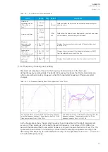
AQ -200 series devices have a measurement accuracy that is independent of the system frequency.
This has been achieved by adjusting the sample rate of the measurement channels according to the
measured system frequency; this way the FFT calculation always has a whole power cycle in the buffer.
The measurement accuracy is further improved by Arcteq's patented calibration algorithms
that calibrate the analog channels against eight (8) system frequency points for both magnitude and
angle. This frequency-dependent correction compensates the frequency dependencies in the used,
non-linear measurement hardware and improves the measurement accuracy significantly. Combined,
these two methods give an accurate measurement result that is independent of the system frequency.
Troubleshooting
When the measured current, voltage or frequency values differ from the expected values, the following
table offers possible solutions for the problems.
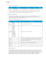
Problem
Check / Resolution
The measured current or
voltage amplitude is lower
than it should be./
The values are
"jumping" and are not
stable.
The set system frequency may be wrong. Please check that the frequency settings match the
local system frequency, or change the measurement mode to "Tracking" (
Measurement
→
Frequency
→
"Smpl mode") so the relay adjusts the frequency itself.
The frequency readings
are wrong.
In Tracking mode the relay may interpret the frequency incorrectly if no current is injected into the
CT (or voltage into the VT). Please check the frequency measurement settings (
Measurement
→
Frequency).
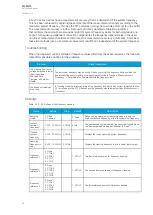
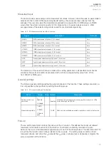
Settings
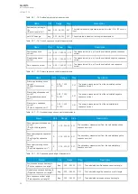
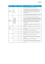
Table. 5.2.2 - 25. Settings of the frequency tracking.
Name
Range
Step
Default
Description
Sampling
mode
0: Fixed
1: Tracking
-
0: Fixed
Defines which measurement sampling mode is in use: the
fixed user-defined frequency, or the tracked system frequency.
System
nominal
frequency
7.000…75.000Hz 0.001Hz 50Hz
The user-defined system nominal frequency that is used when
the "Sampling mode" setting has been set to "Fixed".
Tracked
system
frequency
0.000…75.000Hz 0.001Hz -
Displays the rough measured system frequency.
Sampling
frequency in
use
0.000…75.000Hz 0.001Hz -
Displays the tracking frequency that is in use at that moment.
Frequency
reference 1
0: None
1: CT1IL1
2: CT2IL1
3: VT1U1
4: VT2U1
-
1: CT1IL1
The first reference source for frequency tracking.
Frequency
reference 2
0: None
1: CT1IL2
2: CT2IL2
3: VT1U2
4: VT2U2
-
1: CT1IL2
The second reference source for frequency tracking.
Frequency
reference 3
0: None
1: CT1IL3
2: CT2IL3
3: VT1U3
4: VT2U3
-
1: CT1IL3
The third reference source for frequency tracking.
A
AQ
Q-M210
-M210
Instruction manual
Version: 2.04
65
Содержание AQ-M210
Страница 1: ...AQ M210 Motor protection IED Instruction manual ...
Страница 308: ...Figure 7 4 182 Example block scheme A AQ Q M210 M210 Instruction manual Version 2 04 307 ...
Страница 329: ...Figure 8 13 204 Panel cutout dimensions and device spacing A AQ Q M210 M210 Instruction manual Version 2 04 328 ...

