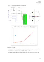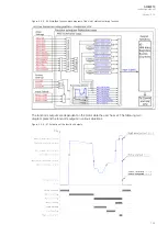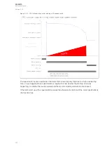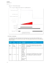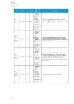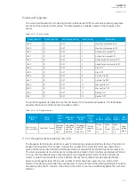
Figure. 5.3.9 - 101. Simplified function block diagram of the motor start/ locked rotor monitoring function.
A recommended setup for this function is for the I
2
t mode to be used in starting; if motor running/
locked rotor situations at times occur in some parts of the duty cycle during normal use, the locked
rotor protection must also be applied. The following five figures present a number of suggested
applications for the Ist> function for various situations. It is advised that the speed switch –if
available– is also used for the motor start monitoring, especially when the motor has a high load when
starting, thus making the start-up take very long.
A
AQ
Q-M210
-M210
Instruction manual
Version: 2.04
134
Содержание AQ-M210
Страница 1: ...AQ M210 Motor protection IED Instruction manual ...
Страница 308: ...Figure 7 4 182 Example block scheme A AQ Q M210 M210 Instruction manual Version 2 04 307 ...
Страница 329: ...Figure 8 13 204 Panel cutout dimensions and device spacing A AQ Q M210 M210 Instruction manual Version 2 04 328 ...


